
https://youtu.be/M3mMAsjv3QE?si=SlriylUZx2sPlxuQ
Workshop System Build Guide 2024-25 Edition ←
The Workshop System is a complete modular synth that you can build in an evening or two.
The four circuit boards are pre-populated with over 650 tiny components. Your job is to attach the interface elements: pots, knobs, switches, sockets (so many sockets), and LEDs.
A few parts of the build are slightly counter-intuitive, so please read this all carefully. If anything is unclear, contact [email protected], ask for help on the Discord, send photos.
NB: This is the build guide for kits bought BEFORE July 2025. For newer kits, use this version. In July 2025, new packing was introduced - more compact and easier to understand.

What you need to know about soldering before you start ←
- To build the Workshop System you’ll need to make almost 400 through-hole solder joints.
- Your joints don’t have to be perfect, but for the system to work, they should all look like one of the ‘OK’ joints in the image above.
- Here is a good seven-minute video introduction to soldering from Curious Inventor.
- I recommend Adafruit’s fantastic Guide To Excellent Soldering. The image comes from the common problems page.
TL;DR Summary for new or nervous builders ←
- If you’ve never soldered before, practise on something else — I always recommend 8mu or Mikrophonie.
- If you’re comfortable soldering but are a new builder, start by watching the build video above. It’s me (Tom, Music Thing Designer) talking through the entire build process in real time. Maybe the closest thing you can get to an online build workshop.
- That video is the same length as Gladiator or Pulp Fiction, but not quite as dramatic.
- If you’re uncertain about anything, ask for help before soldering, not after.
TL;DR Summary for experienced builders ←
- If you’re a confident builder, there are a few things that might trip you up. (Two beta builders made the same mistake, based on an assumption)
- There are four different types of potentiometer, and six different values. They’re all marked on the PCB — make sure the right pot is in the right place
- There are three different types of toggle switch. They look the same but feel and work differently. One has a specific orientation. It’s all marked on the PCB but make sure you understand my weird symbols.
- There are two different tactile switches, one 12mm long, one 13mm long.
- Longer legs on LEDs are marked with a + symbol.
- There are three green (stereo) sockets.
- If you understand all that, it’s a very straightforward build. You’ll probably be fine.
- You can calibrate your system once you’ve finished.
Contents ←
- What do I need to build the Workshop System?
- Assemble the case
- Assemble the power supply
- Prepare the front panel
- Understanding the parts
- Starting to build
- Recommended build order
- Power headers and switch prep
- Build the VCO
- Build Computer
- Build Mix
- Build the VCF
- Putting it all together
- Calibration
- Troubleshooting
- Modifying and personalising your system
Before you start ←
- Sign up for the Workshop System Newsletter - for new program cards, gigs, demos, patch ideas, collaboration opportunities, workshops and so on.
- Join the Workshop System Discord - musicians and coders using and developing the system.
What do I need to build the Workshop System? ←
Apart from the kit, you’ll need:
- A USB-C PD power supply that can give 15 Volts, to power the system when you’re finished. Full power details.
- A soldering iron. Something with temperature control and a clean fine tip. It doesn’t need to be tiny, but shouldn’t be huge.
- Solder, either leaded or unleaded, with the soldering iron set to the appropriate temperature
- A tip cleaner, I use brass wool, some people use a sponge
- A small cross-head screwdriver
- Some tape or blu-tack to hold parts in place. I use thin Kapton tape which is cheap and heat resistant, but you can use any kind of masking tape.
- A Sharpie or something else to sign the PSU board
- Some double-sided tape or epoxy glue to attach the label to the case
- Enough light and magnification so you can see small things clearly
- Enough ventilation so you don’t have solder fumes in your face. I use a small desktop fan and an open window.
- Space and time and a clear head.
Assemble the case ←
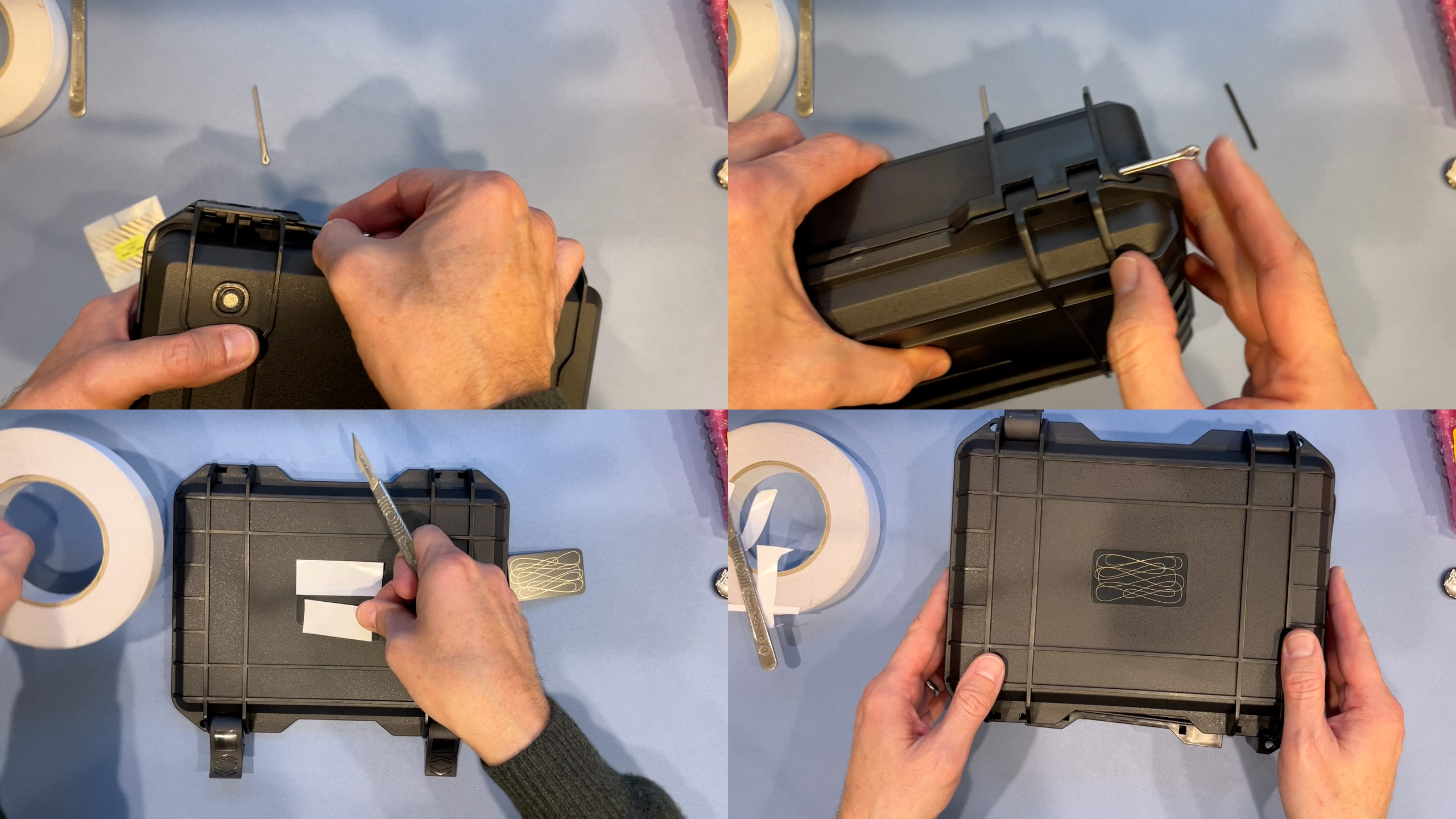
- VIDEO LINK: Assembling the case.
- From the factory, the case lid is attached with two 3mm plastic pins.
- Swap these for the attached steel pins, so the lid is easier to remove. Just use the steel pin to push out the plastic, then replace it.
- The kit also includes a label for the case.
- Either use epoxy glue - put a weight on the label while the glue sets. Or use double-sided tape, cut to size.
- I also used double-sided tape to stick the case foam into the box. Check the larger hole lines up with the Stompbox power outlet.
- The kit includes eight stick-on rubber feet. Four for the case, four for the system itself.
Assemble the Power Supply ←
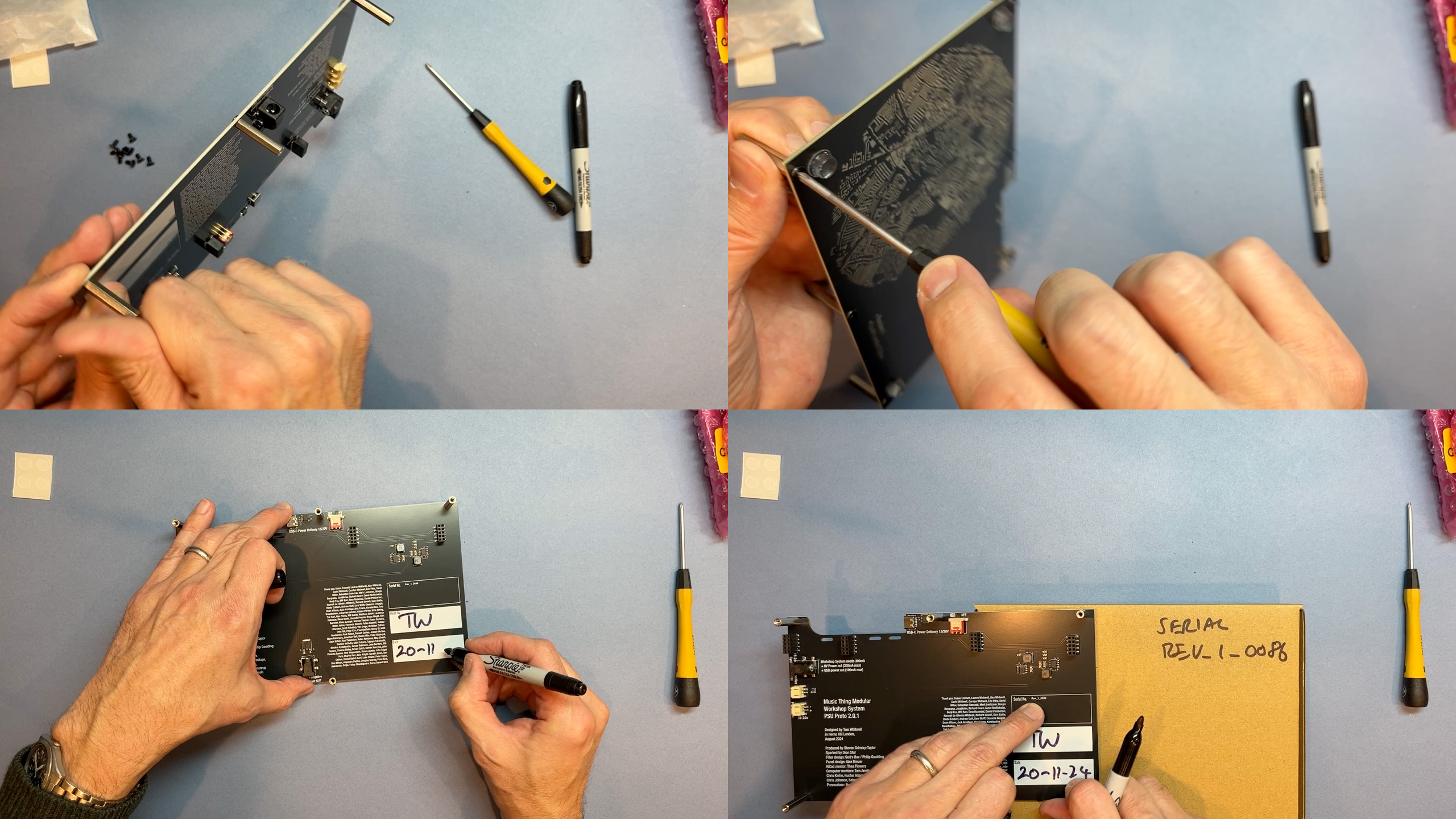
- VIDEO LINK: Assembling the PSU.
- Stick the rubber feet onto the PSU board
- Screw the six hexagonal spacers onto the PSU board
- Don’t forget to sign and date the PSU board
- Make a note of the serial number
Prepare the Front Panel ←
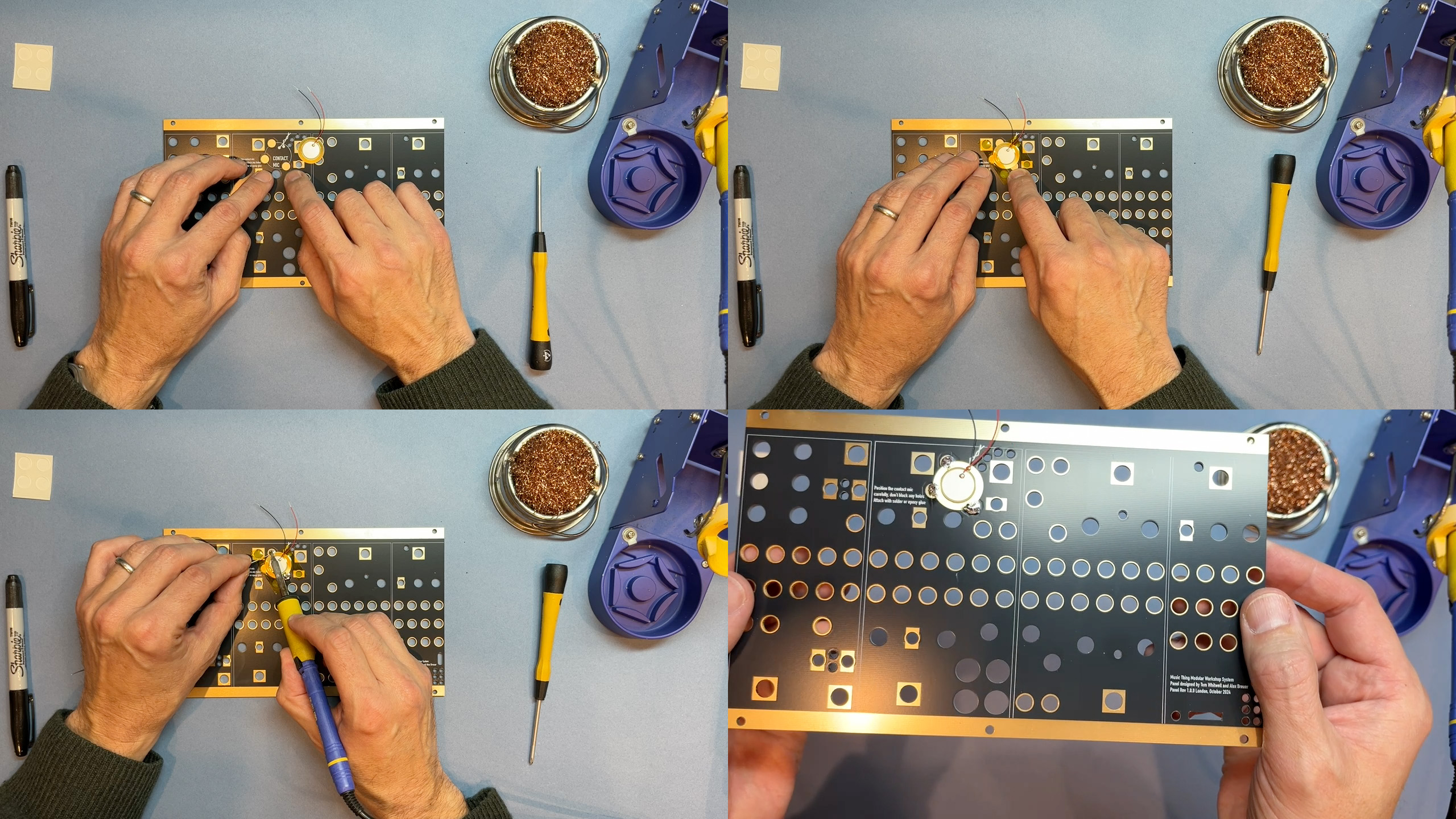
- VIDEO LINK: Soldering the piezo mic
- Before soldering the rest of the kit, attach the small brass piezo microphone to the front panel.
- You can use solder or epoxy or superglue to do this
- The position is marked. Tape the disk down and solder the three marked points. It’s quite a large area, so hold the soldering iron down for 5-10 seconds to heat it through before trying to solder.
- You might want to tape the wires down to keep them out of the way for the rest of the build.
Understanding the parts ←
Before we starting to build the circuit boards, take a few minutes to understand the components we’ll be using.
In this section of the build video, I talk through and explain all the parts on a complete Workshop System, explaining what goes where and what to look out for.
Understanding power headers ←
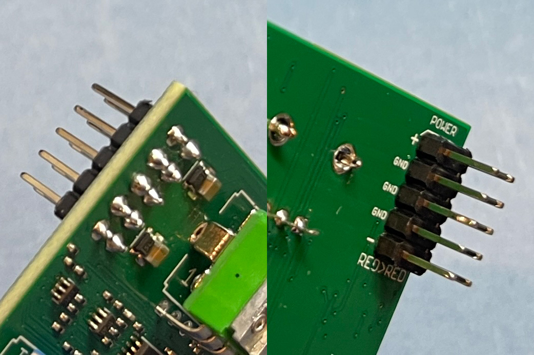
- There are 4 x power headers, one for each PCB
- Power Headers come out of the back of each module - on the opposite side to the pots and sockets
- This means that solder points are on the front of the PCB, next to the tiny surface mount components
- If you are in any doubt at all, please check before soldering - [email protected]
- Every time we run a workshop, someone puts the power header on the wrong side, and it’s very frustrating for them to fix.
Understanding pots ←
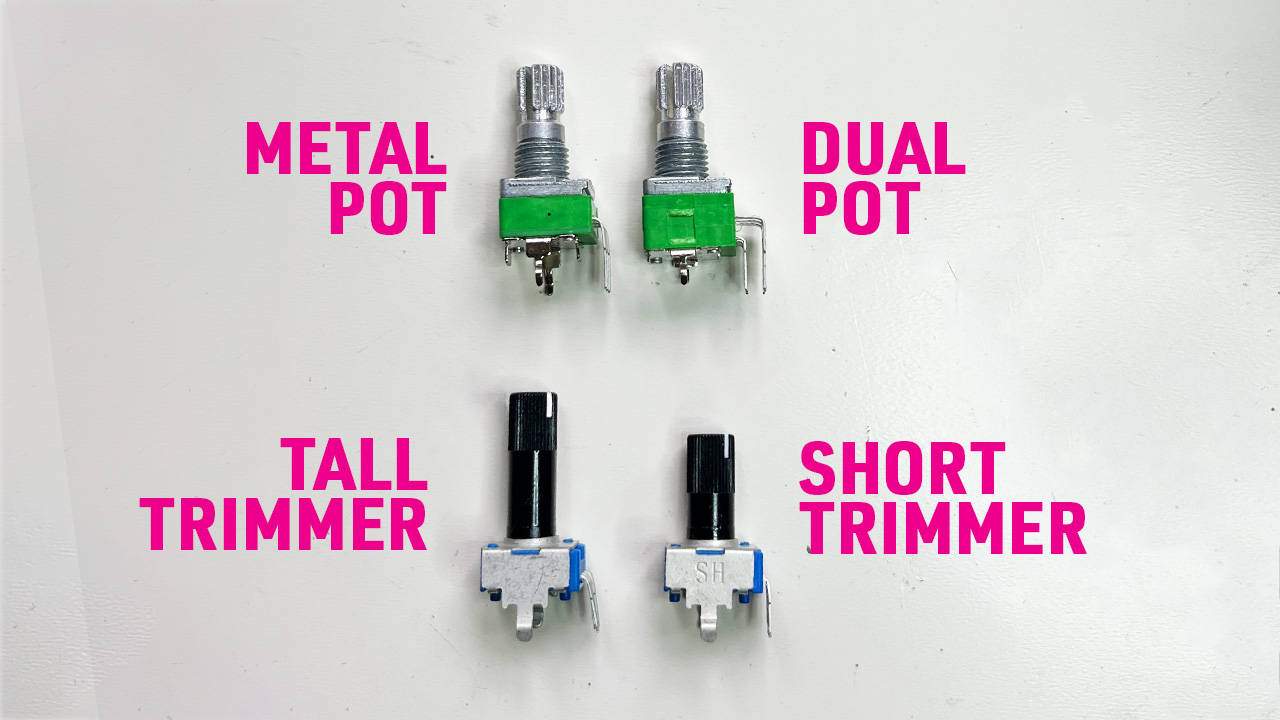
- There are four different types of pot in the workshop system.
- Make sure you know which pot goes in which space. It’s difficult and annoying to remove and replace a pot.
- Metal Pots are standard high quality 9mm pots with three connections and two legs and a ‘knurled’ metal shaft for the knobs
- Dual Pots are also metal, but have six connections. There are two Dual Pots, one is the master stereo volume control, the other is in Amplifier.
- Tall Trimmers are plastic pots with longer shafts, generally used in hard-to reach parts of the system.
- Short Trimmers are plastic pots with shorter shafts, used around the edges of the system.
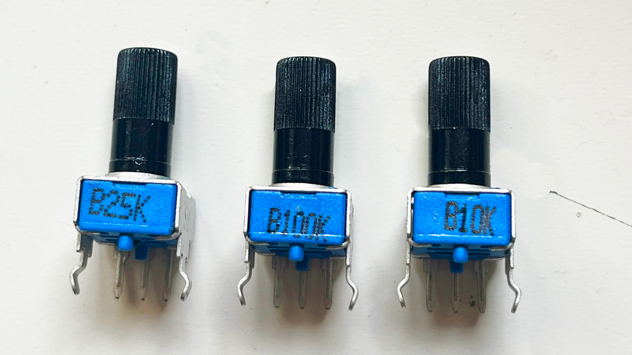
- But wait: Pots also come in different values.
- Metal Pots are all B100K
- Dual Pots can be A100K or A1M
- Tall Trimmers can be B100K or A1M
- Short Trimmers can be B100K, B25K, B10K
- Please put the right pot of the right value in the right spot!
Understanding switches ←
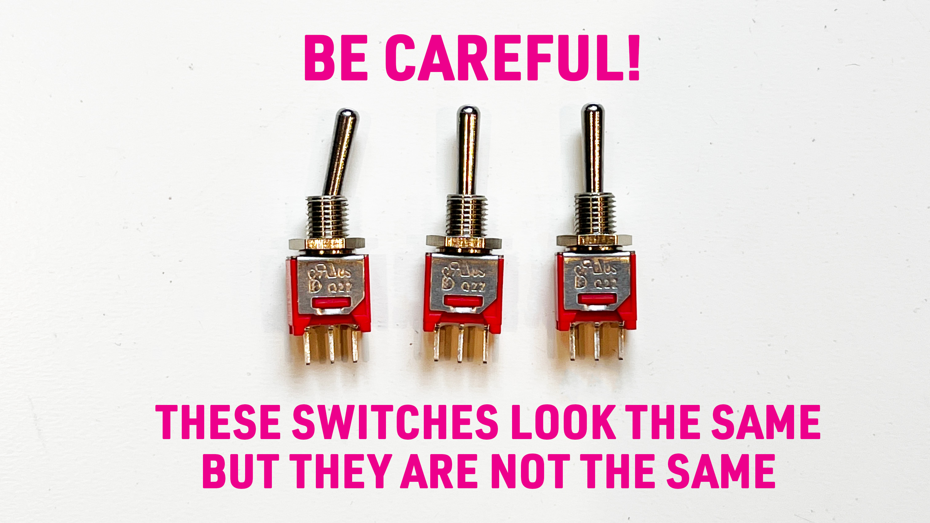
- There are three types of toggle switch in the workshop system
- Two of them look exactly the same but are very different so really please don’t mix them up
- ON-ON switches have two positions. They’re always at an angle. They’re only in the Filter module. They’re a bit annoying to fit through the panel. It doesn’t matter which way round you put them.
- ON-OFF-ON switches have three positions: Up, Middle, Down. It doesn’t matter which way round you put them.
- ON-OFF-MOM switches have three positions, but one is momentary. It doesn’t latch. You can only tell the difference by feeling them, moving the toggle. NB: The direction of this type is very important, and clearly marked on the PCB.
- Please put the right switch in the right spot, the right way round!
Understanding LEDs ←
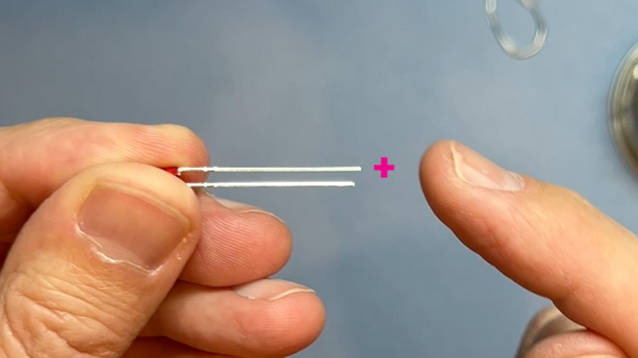
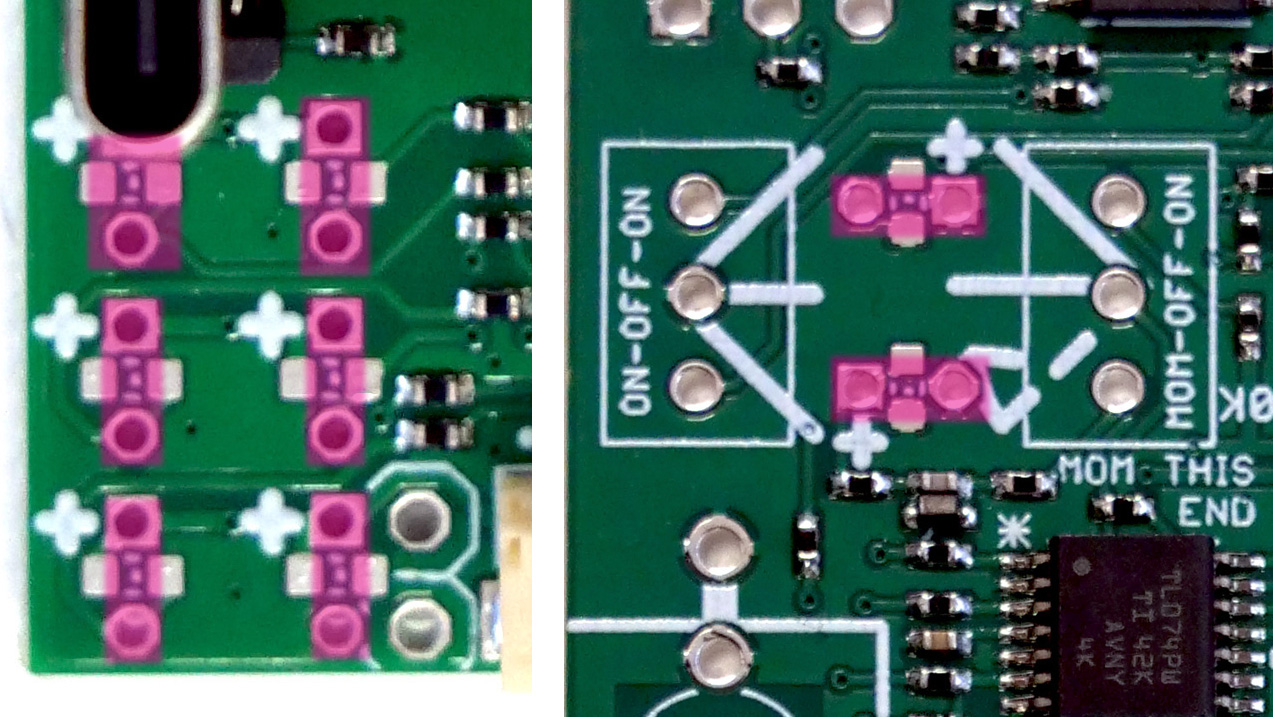
- All the Workshop System LEDs are the same
- Direction is very important. The long leg goes in the hole marked +.
- You never need to bend out the LED legs, they always go into two pins next to each other.
- The LEDs have flat tops which should be flush with the panel. Use a piece of tape or blu-tack to line them up before soldering, and check twice before cutting off the legs.
- NB: from 2025, kits include three tiny plastic spacers to protect the legs of Computer LEDs. How to install the LED spacers.
Understanding sockets ←
- The Workshop System has two types of sockets: Black sockets which are mono, and green sockets which are stereo.
- The green sockets are clearly marked, everything else is black.
Starting to build ←
Build your boards in this order:
- VCO / Oscillator The oscillator board has no LEDs, no switches so it’s a good place to start.
- Computer Just six LEDs and one momentary switch, it’s a quick easy build
- Mix Two types of switches, dense pots, but simple enough now you’re more confident.
- VCF / Filters Definitely the fiddliest board mechanically, with ON-ON switches that are tricky to nudge through the panel, close-packed LEDs and pushbuttons.
\
Power headers and switch prep ←
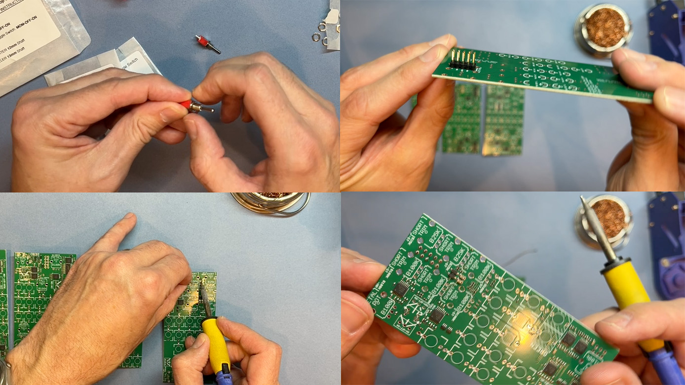
- VIDEO LINK: Soldering headers and preparing switches
- Before starting to build the circuit boards:
- Put one nut from the switch nuts bag onto each switch. This means they’ll be properly spaced behind the panel. NB: Sometimes the nut spins on the switch rather than tightening. That’s not a problem.
- Solder all the power headers. Take your time, the pins are quite large so need a moment to heat up before you apply the solder.
Building the VCO ←
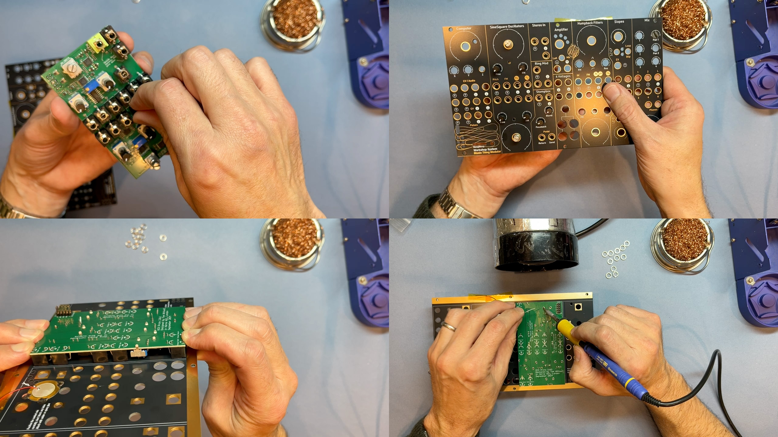
- VIDEO LINK: Building the VCO
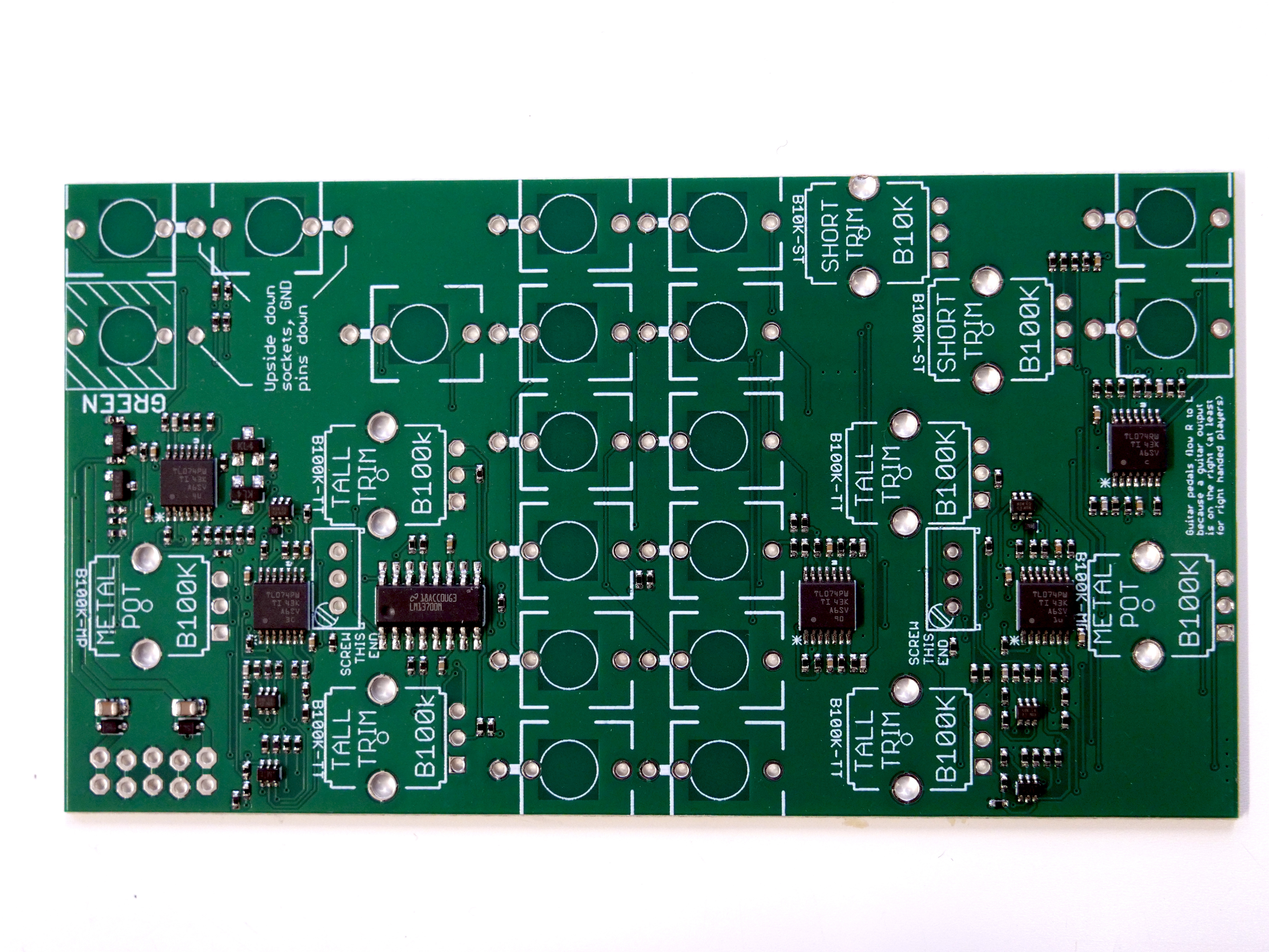
- PCB photos:
- Use this technique for all boards:
- First, mount all the components on the PCB, without soldering anything (apart from the power header, which is already in place)
- Ensure all pots are of the correct type and value
- There is one green socket on this board
- Check the screw trimmers are correctly aligned. The gold screws are marked on the PCB.

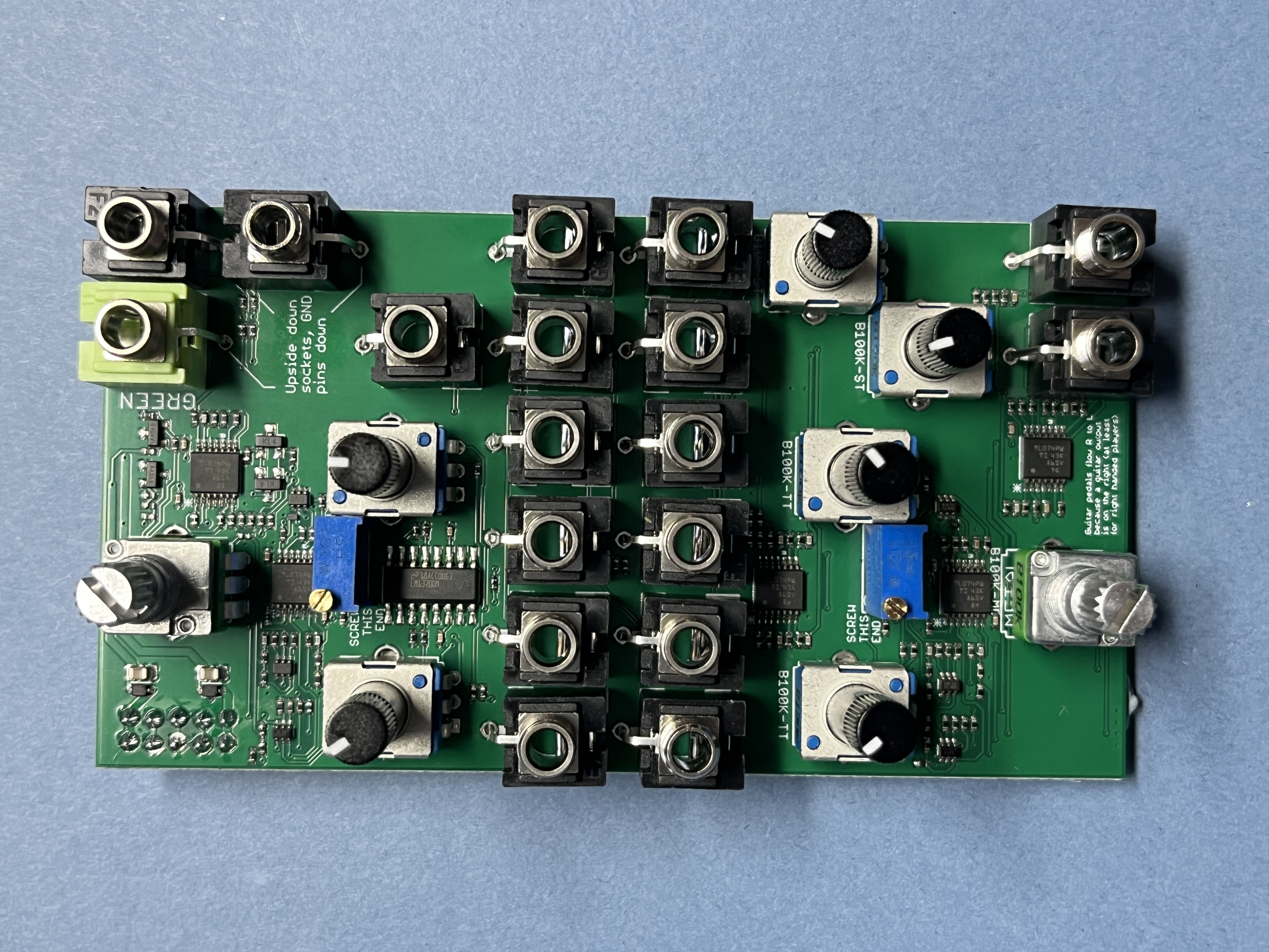
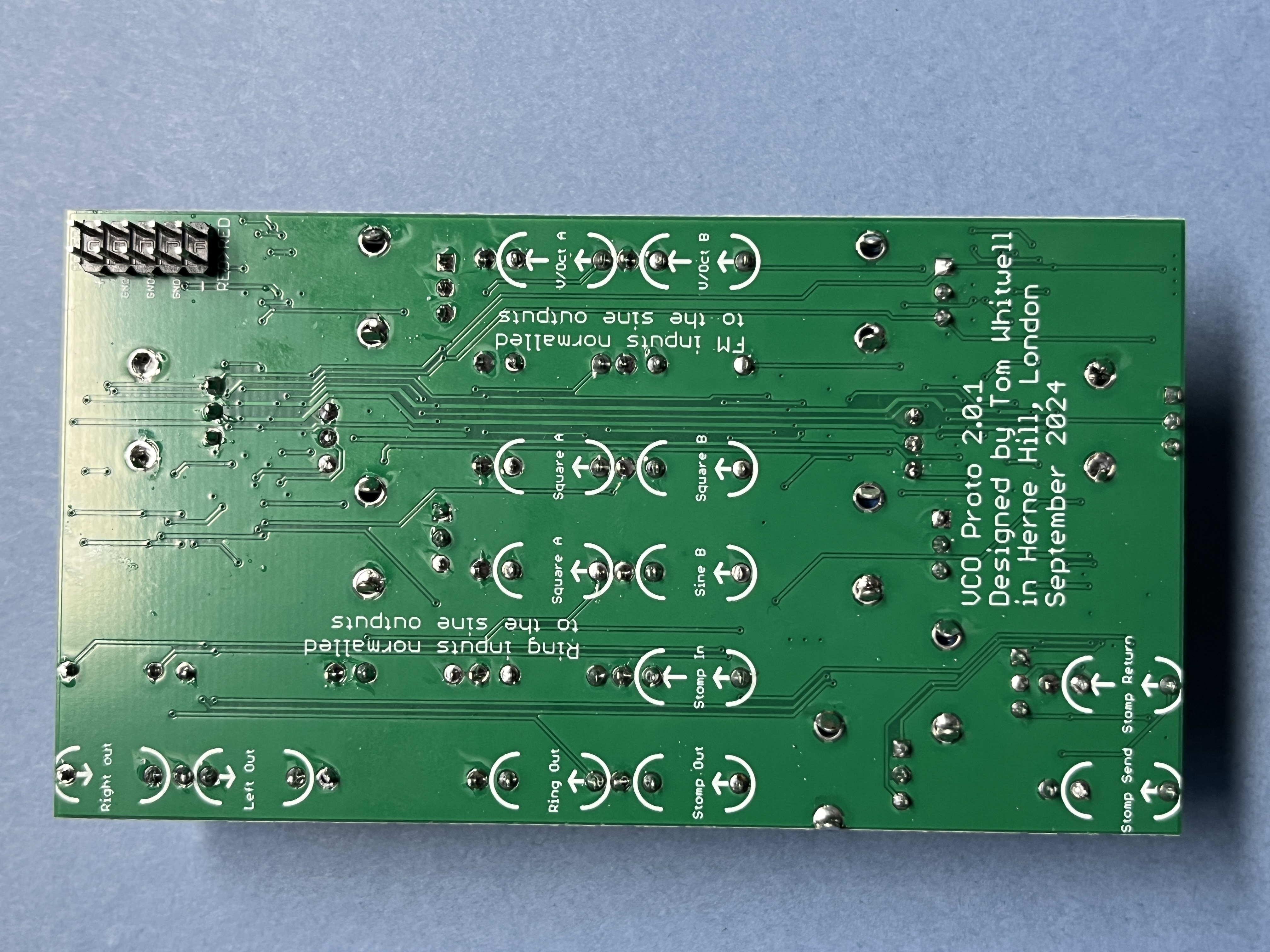
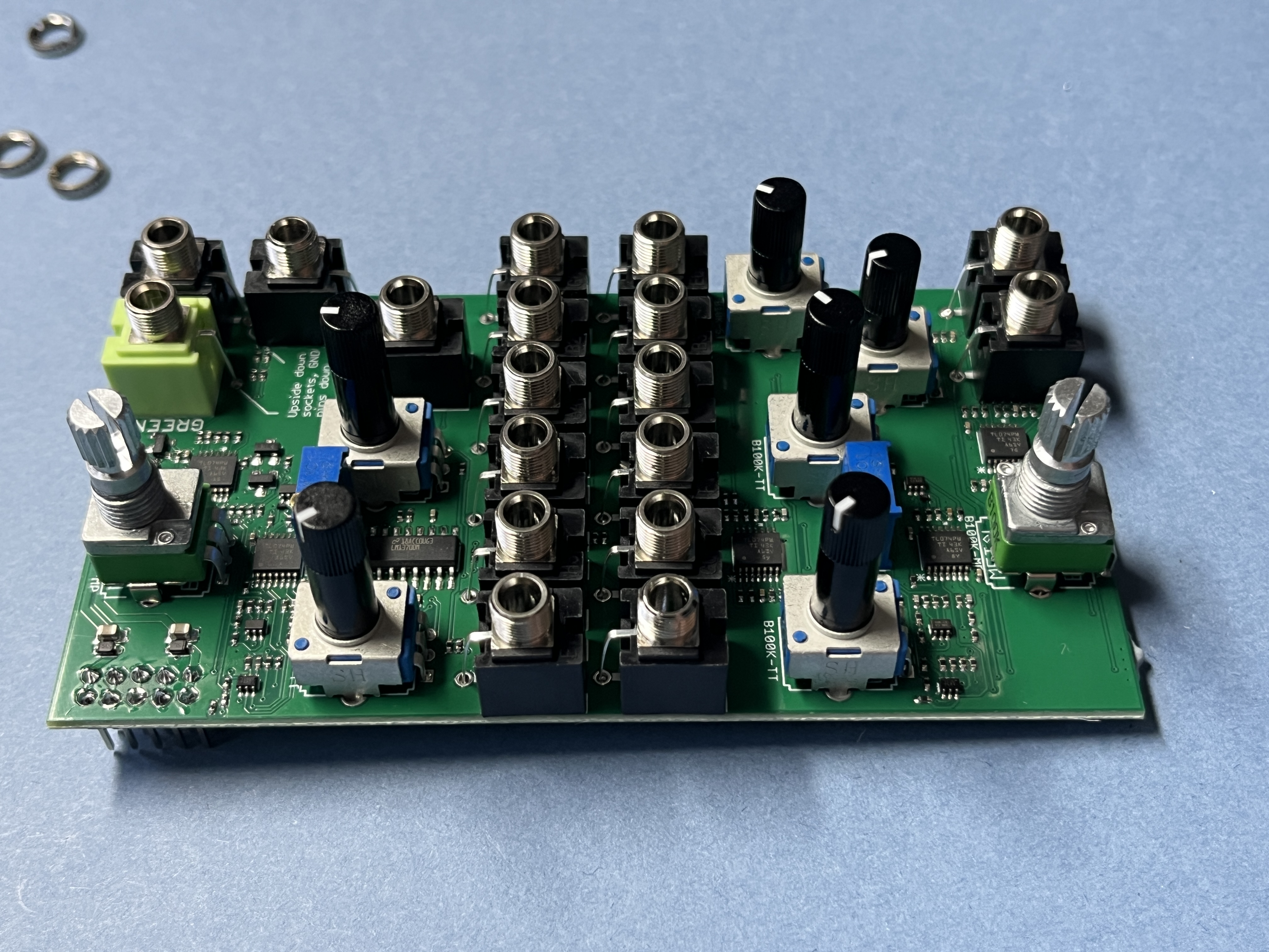
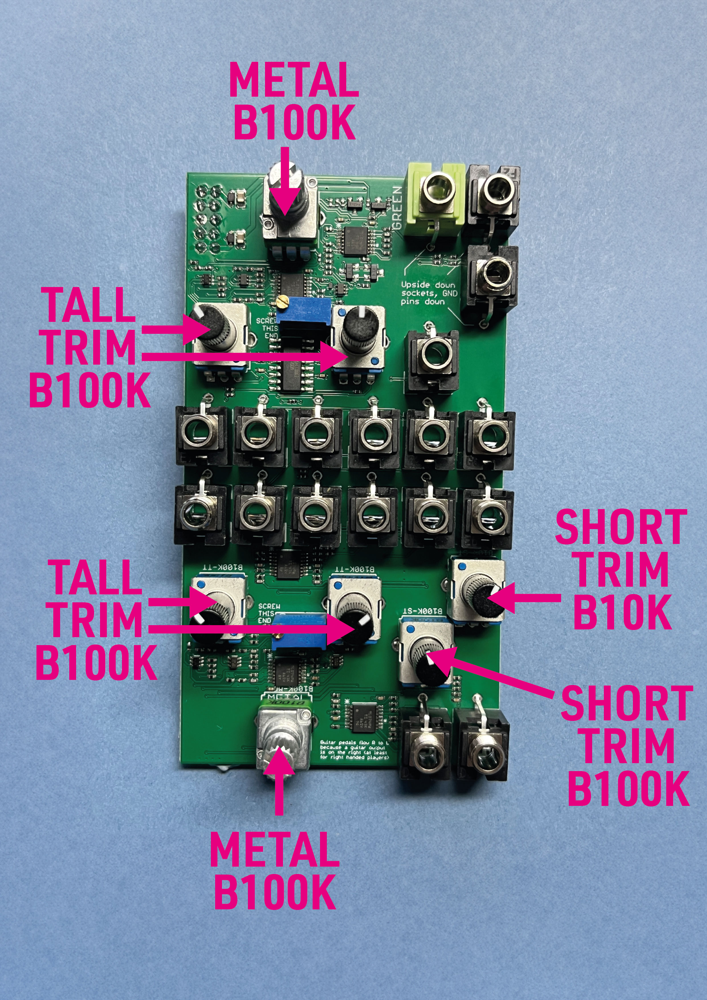
- Before soldering, push the PCB and components onto the panel. Add a couple of nuts to metal pots and a few sockets.
- Check everything is in place: trimmers can all be turned, the little gold screws are through the holes in the panel.
- Ensure the panel is parallel to the board.
- Solder one point on each component. At this point, it’s still easy to move any parts that are wrong. Check again for placement.
- Once you’re happy, go back and solder all the points.
- Double check! At this point I normally use a magnifier to check over all the solder points, touching up any that are blobby or missing.
Building Computer ←
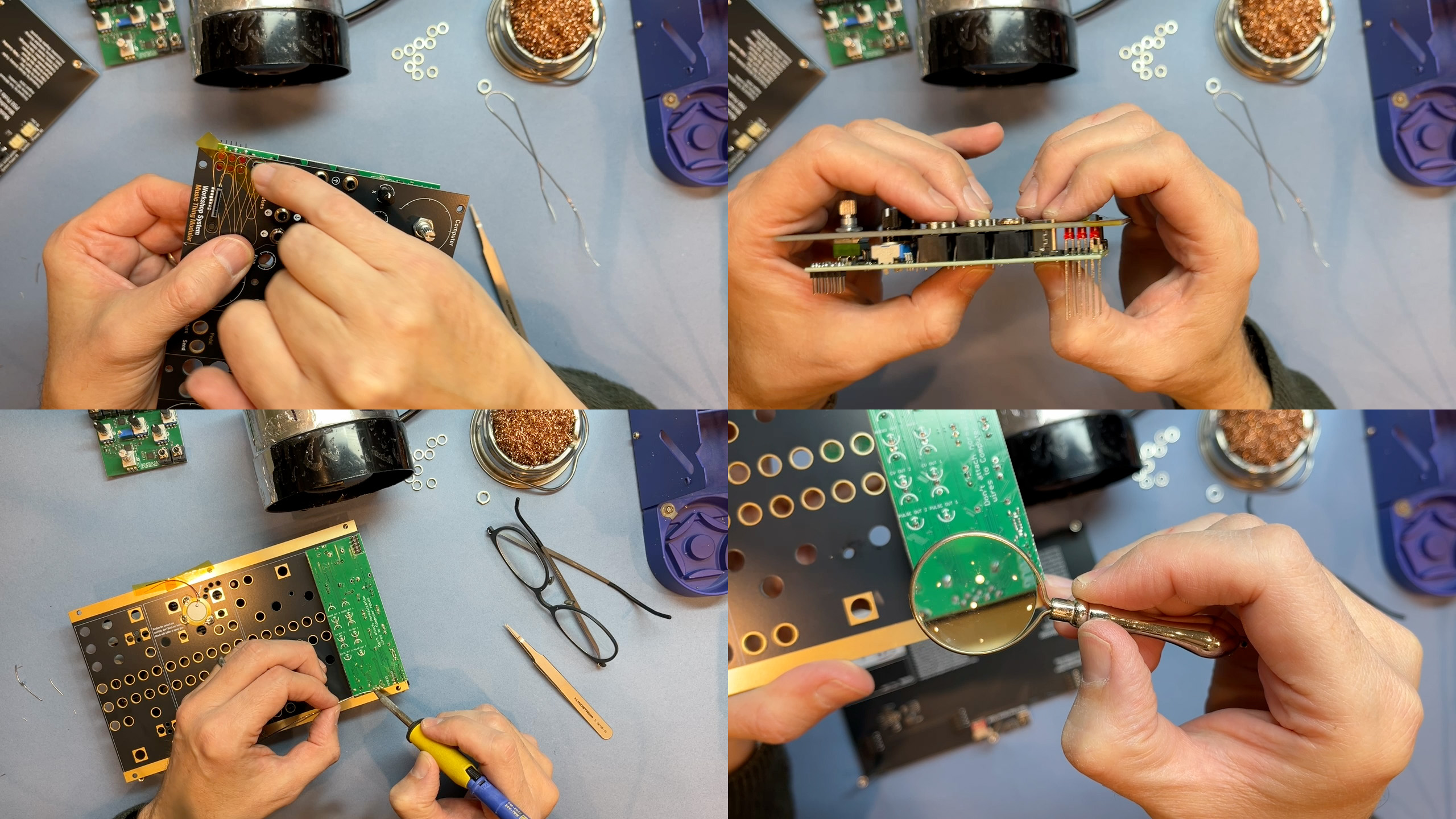
- VIDEO LINK: Building the Computer
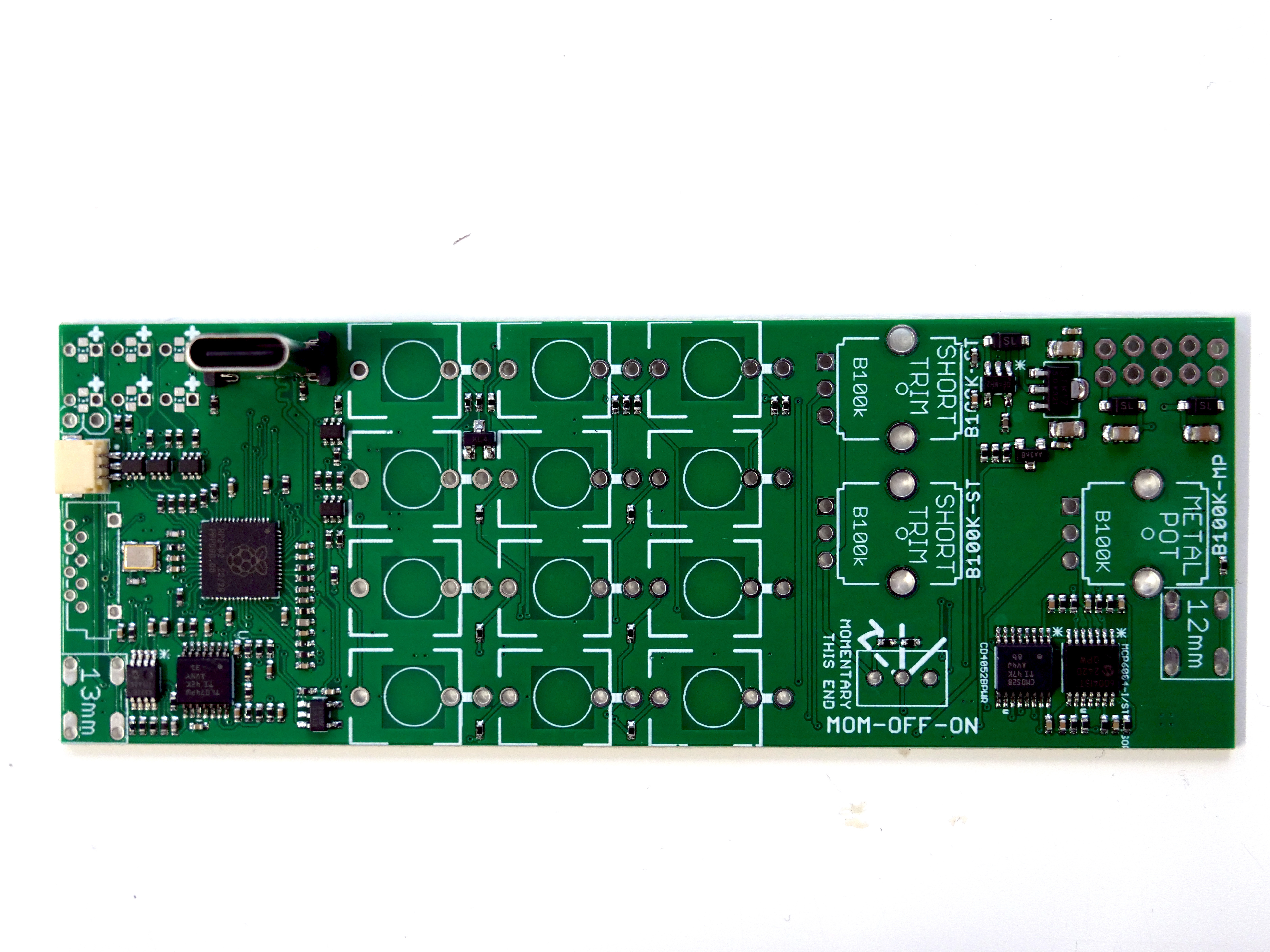
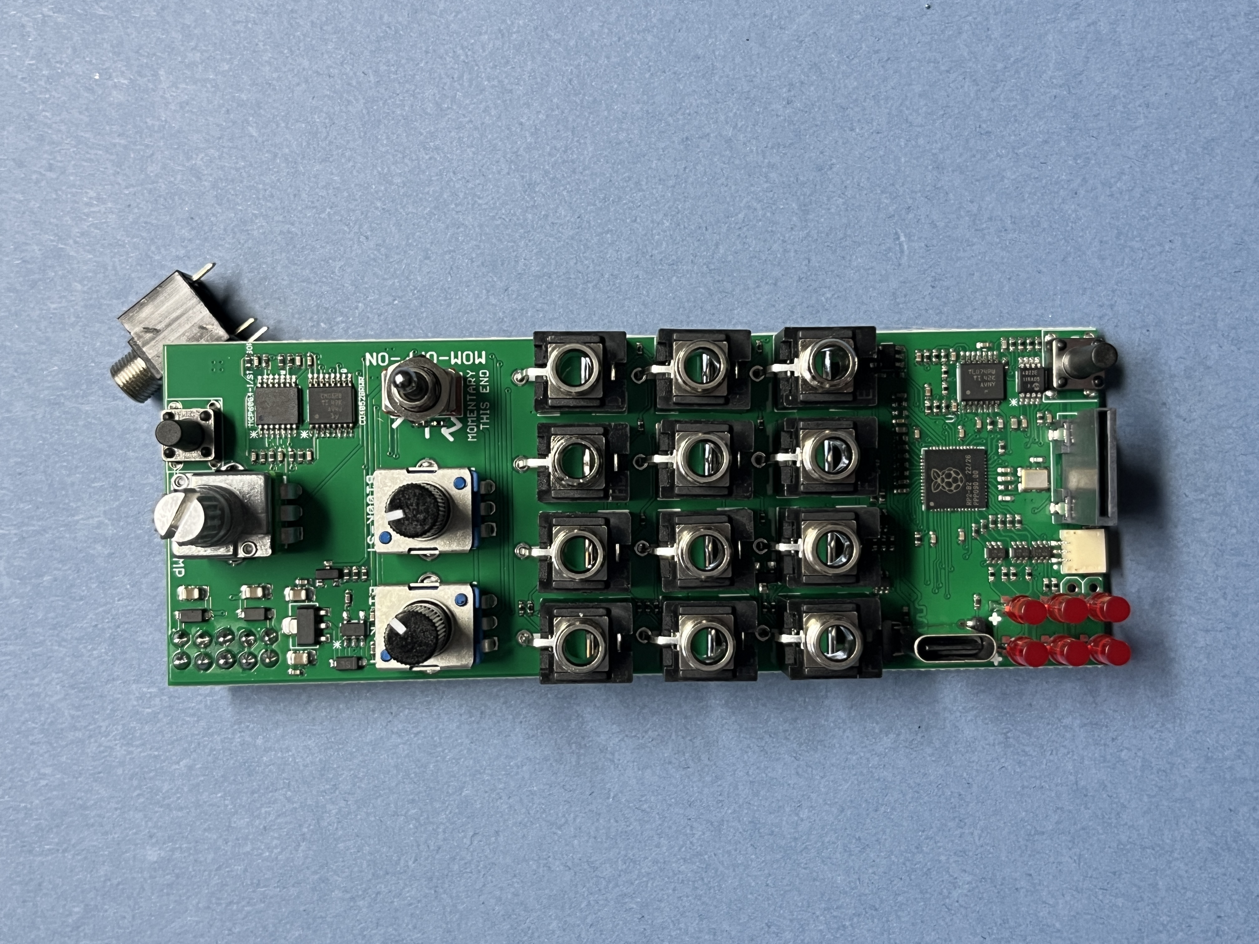
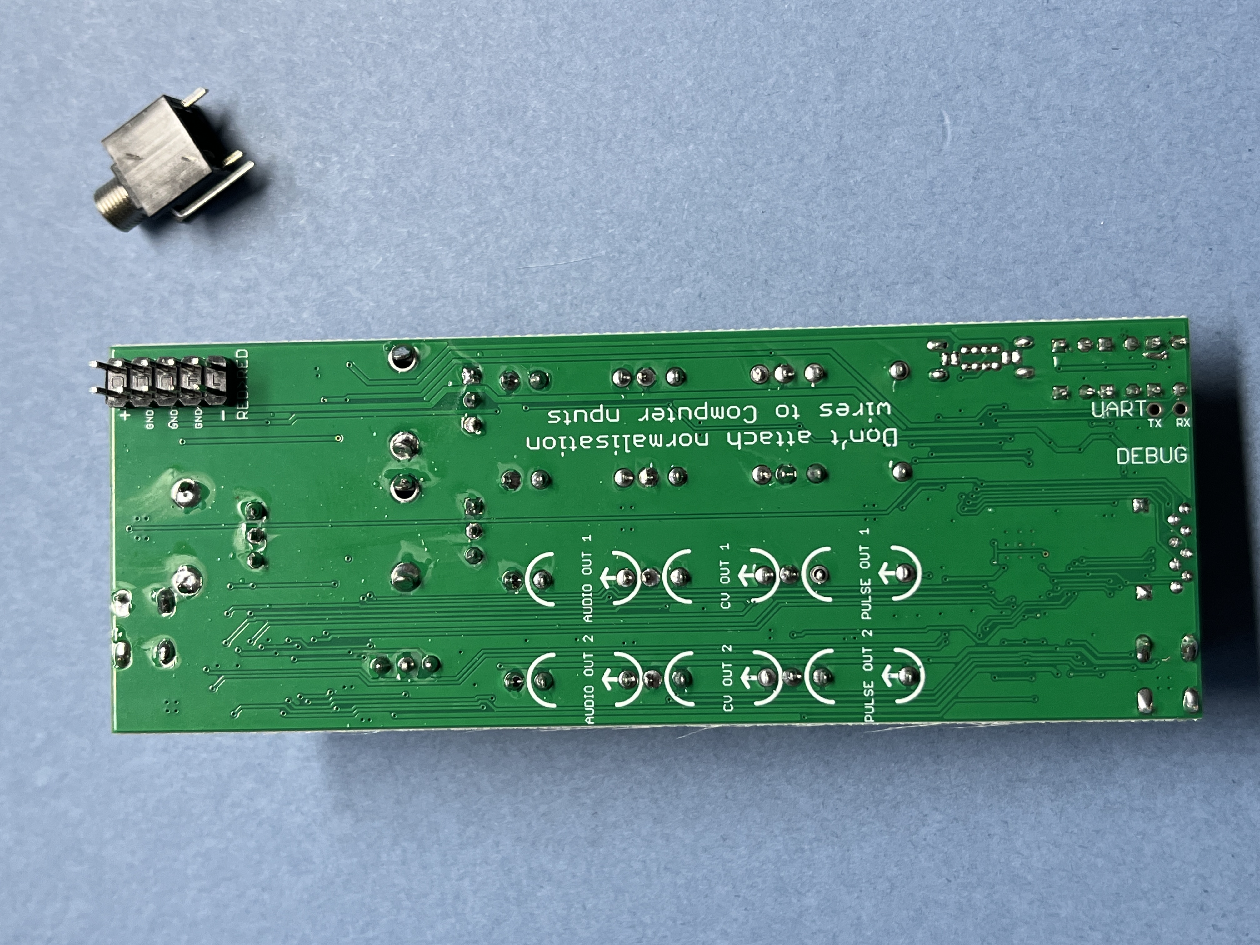
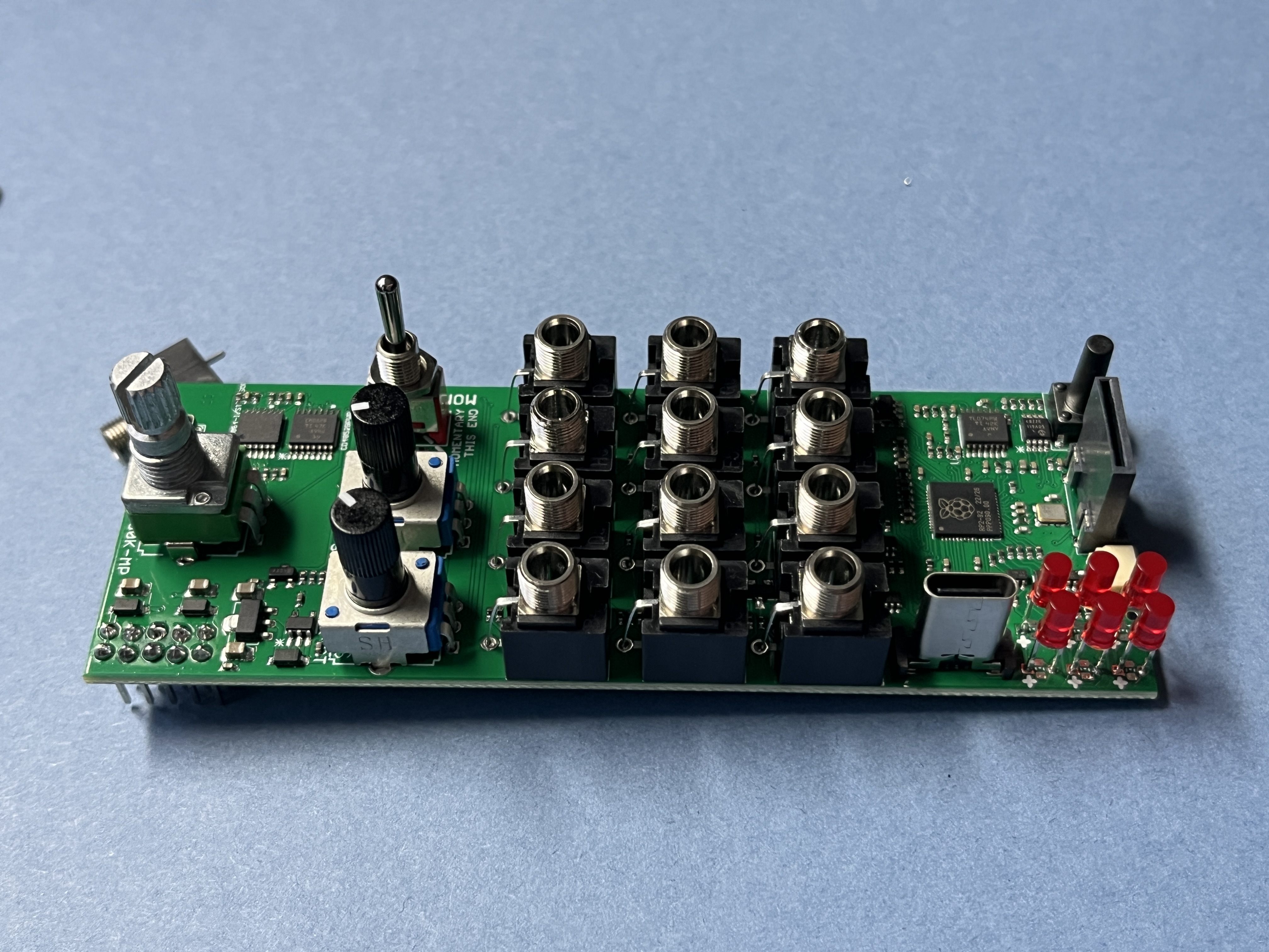
- PCB photos
- Computer is built in exactly the same way, with a few different details
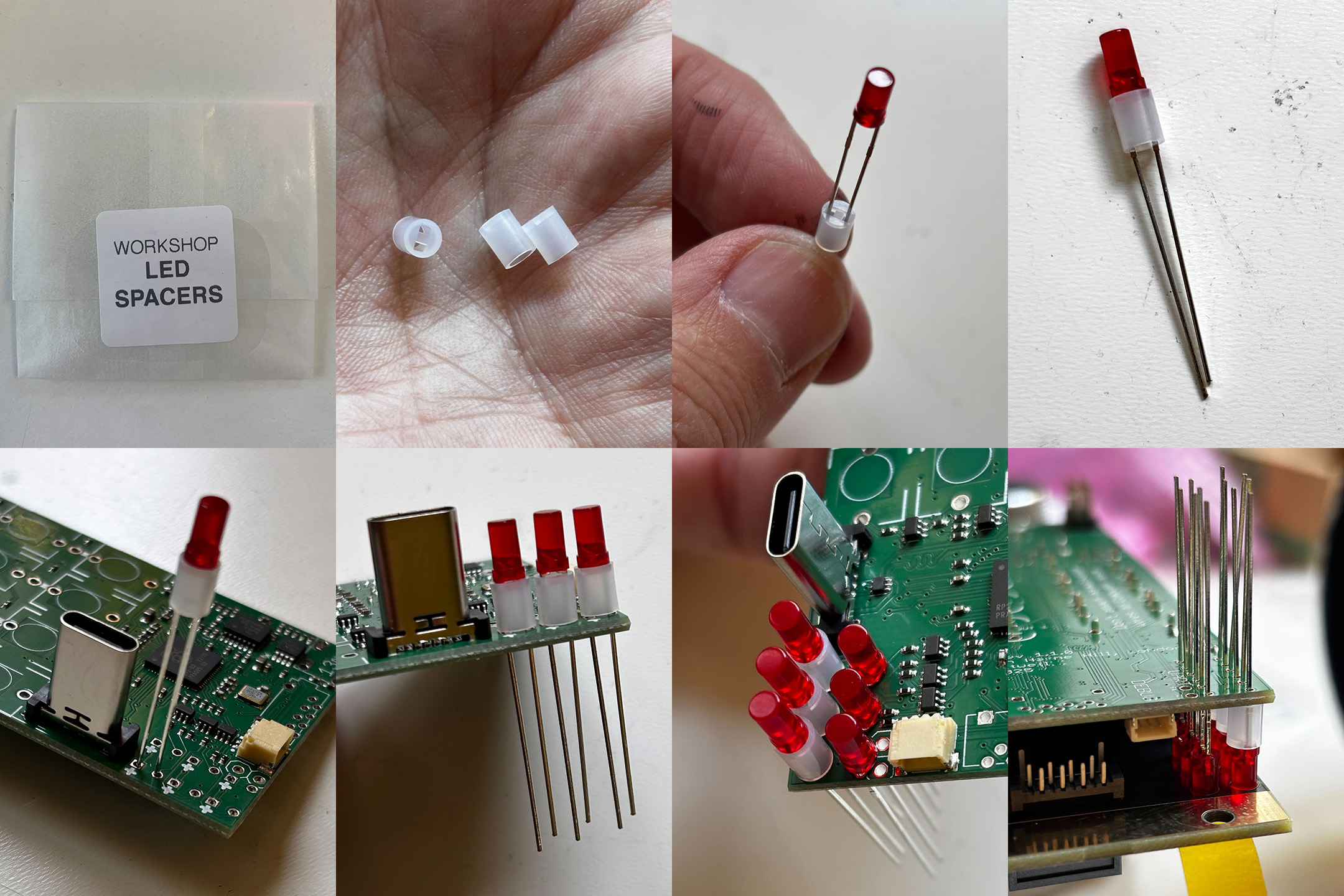
- LED SPACERS From 2025, kits include three tiny plastic spacers to protect the legs of Computer LEDs. Add them to the LEDs on the left hand side of Computer, close to the edge of the PCB. Orientation of the plastic spacers doesn’t matter, but be careful to still put the long legs through the holes marked with +.
- There are two tactile pushbutton switches. They look the same, but one is 12mm long, the other 13mm. The shorter switch goes at the top, behind the main knob.
- The switch is an ON-OFF-MOM. Check that the alignment of the switch - the momentary side - is downward, as marked on the board.
- Use a bit of tape or blu-tack to line LEDs up to the panel before soldering
- Ensure the long LED legs go through the hole marked +. Don’t rush it, it’s annoying to fix later
- The SD Card is a little fiddly. Maybe do this separately, after all the other components. Use a bit of tape or blu-tack to hold it in place. It has very small pins, be careful when soldering to avoid shorts from big solder blobs.
Building Mix ←
- VIDEO LINK: Building Mix
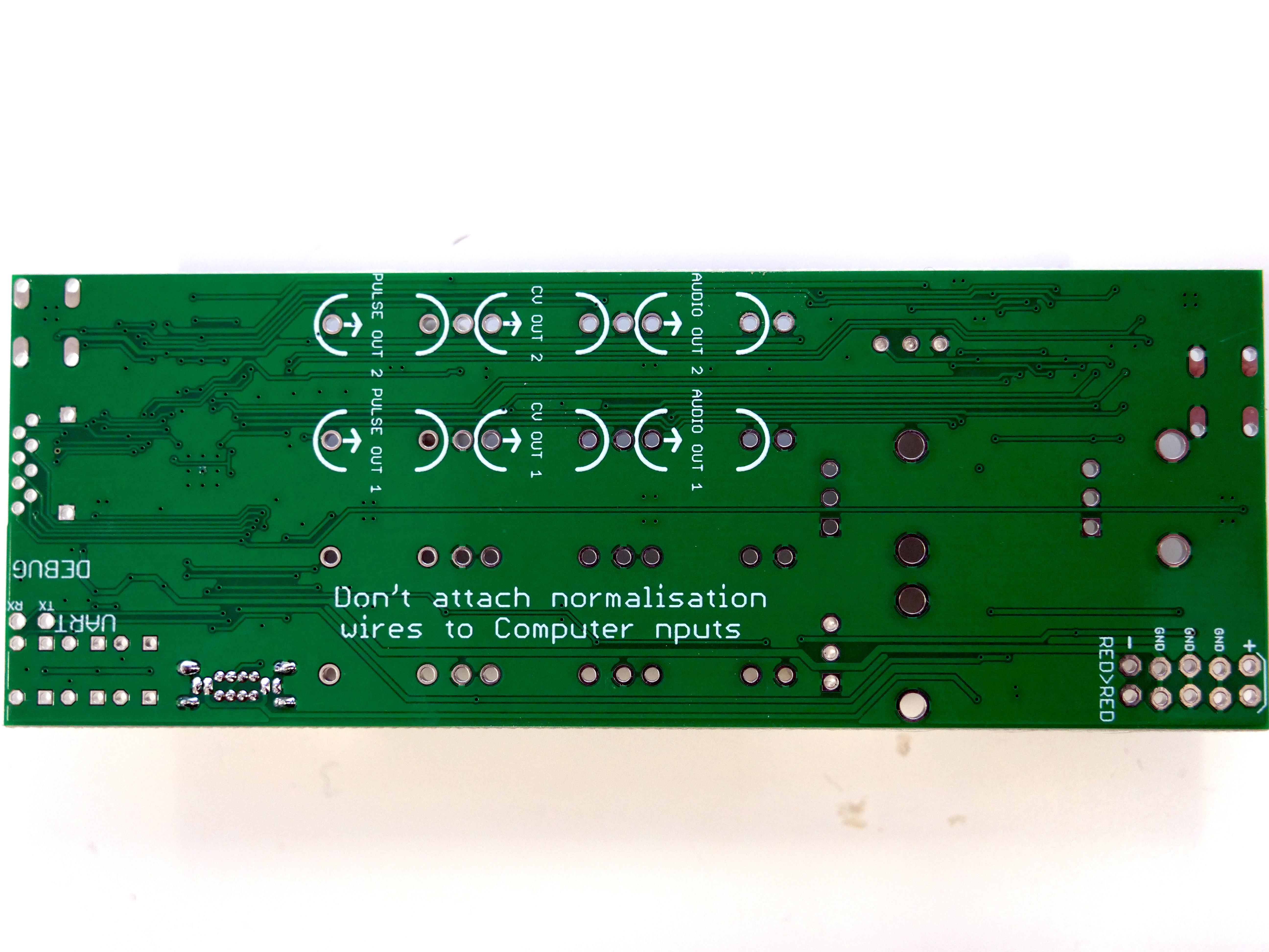
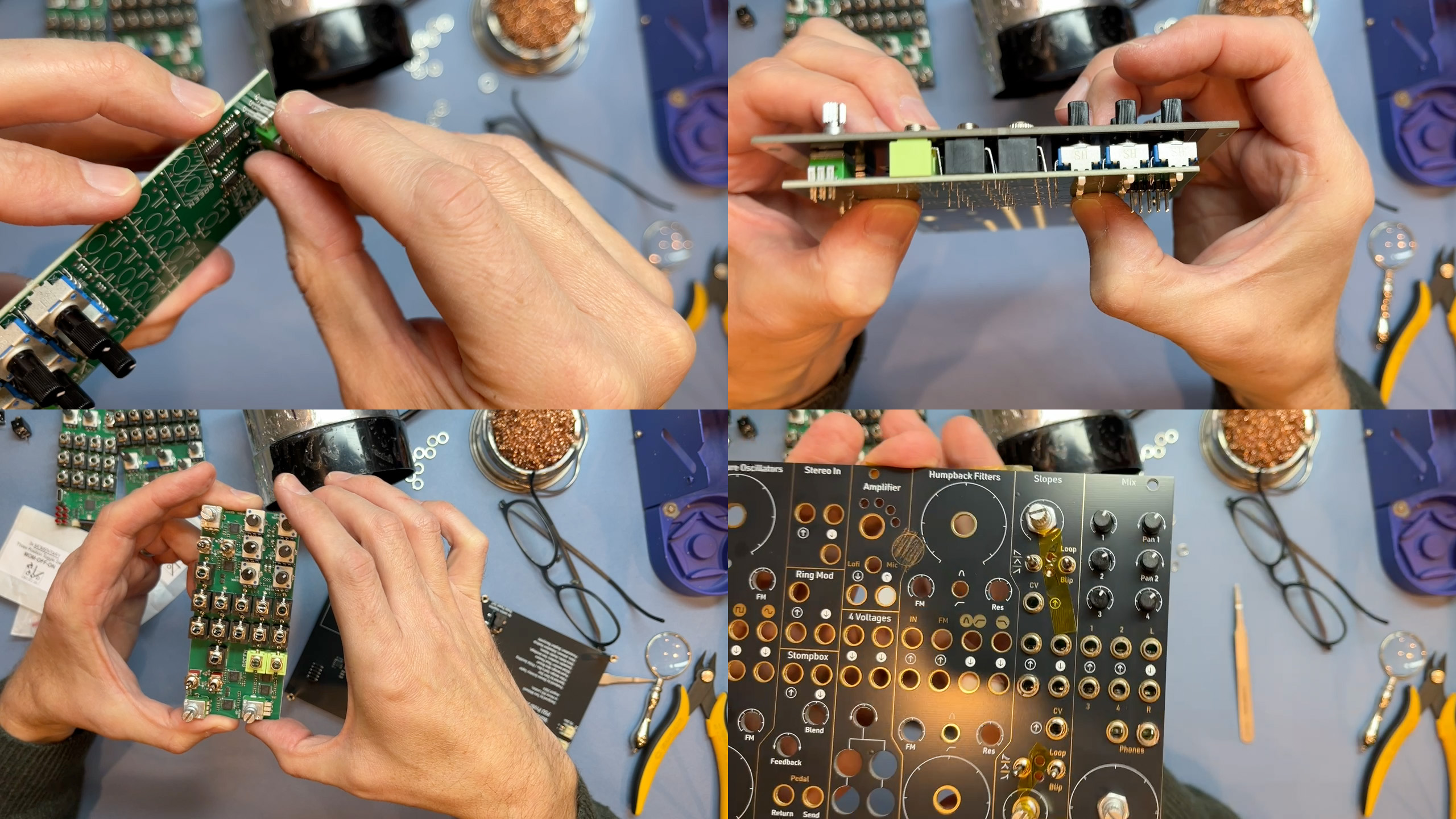
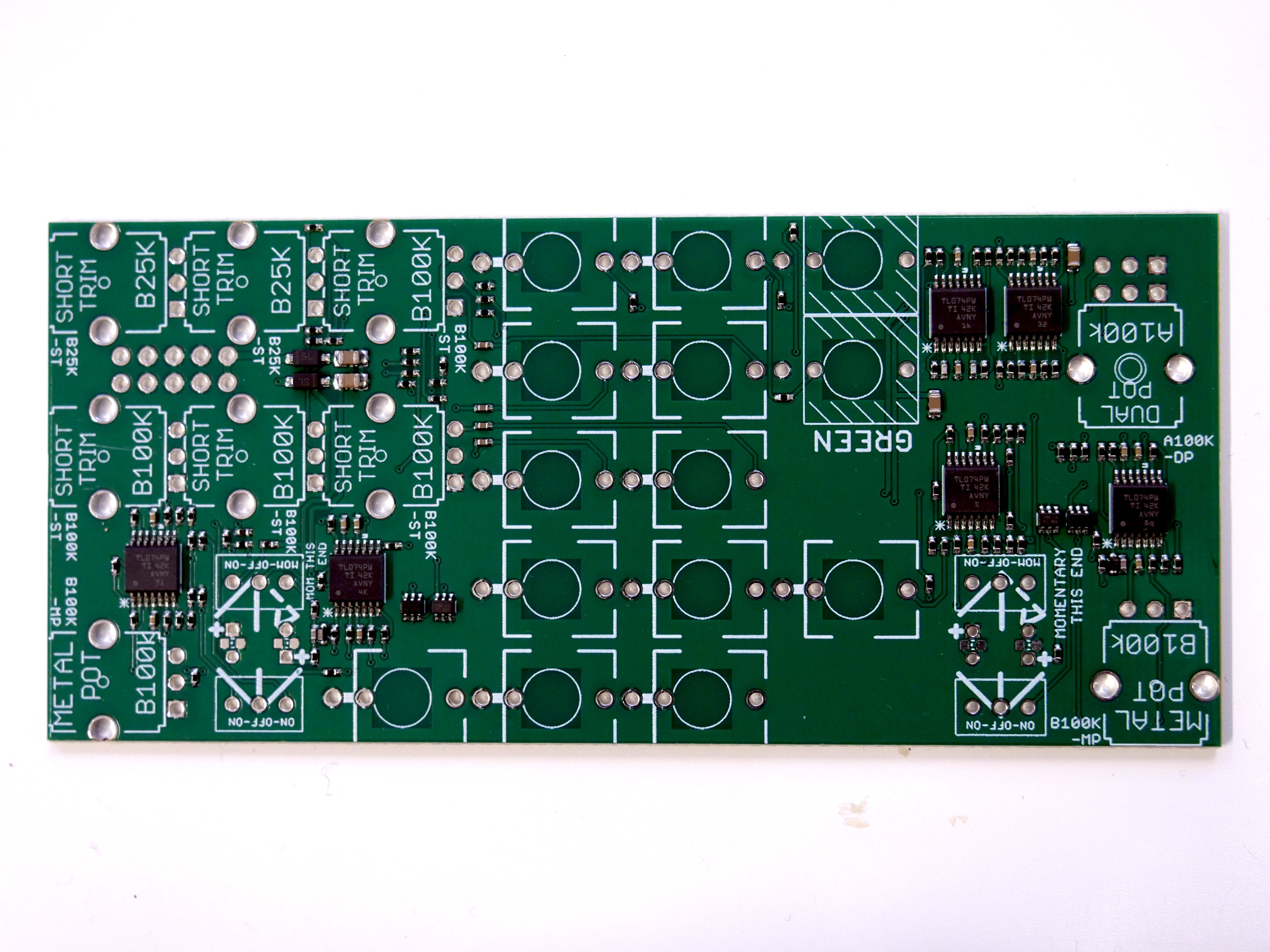
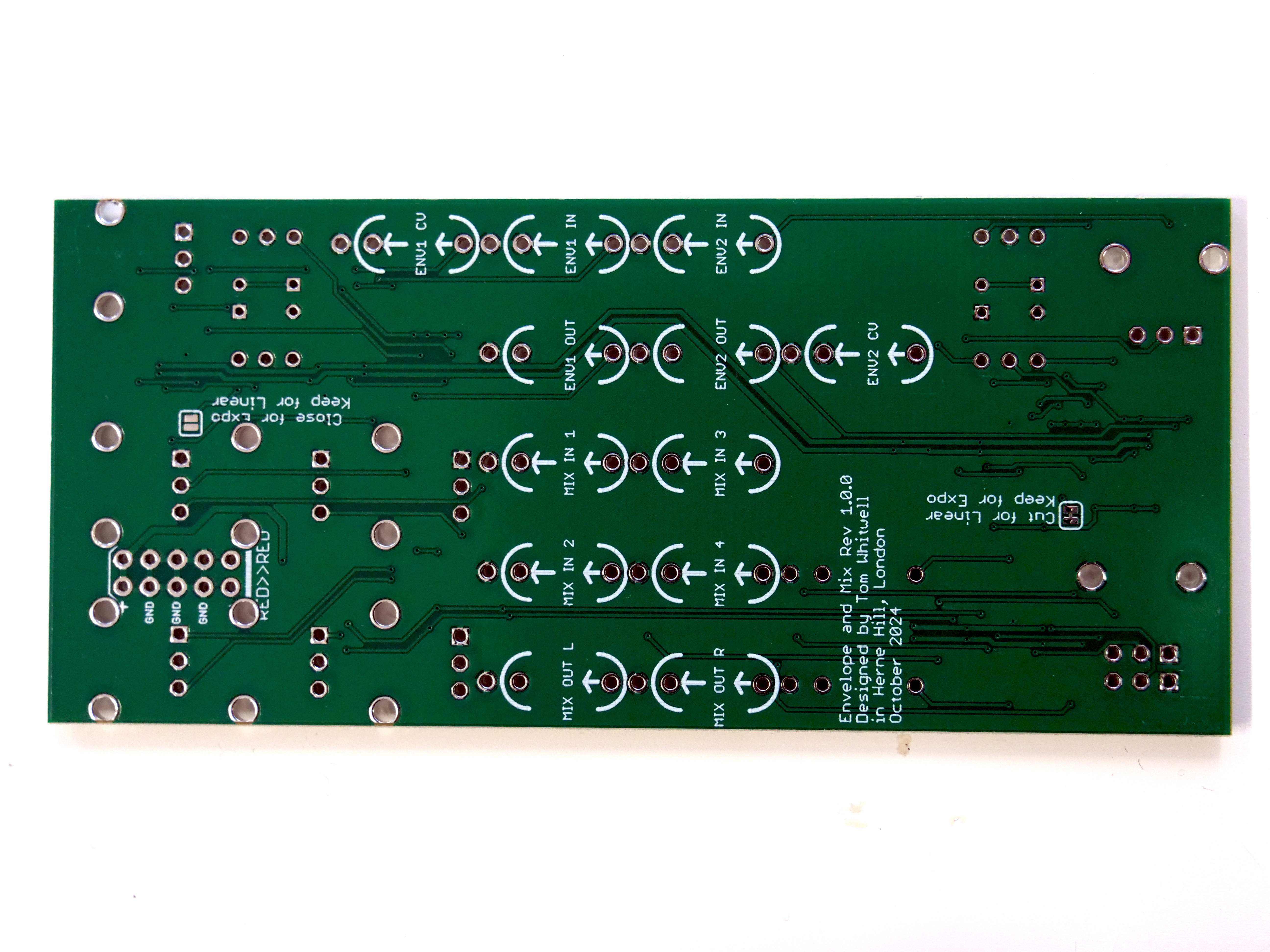
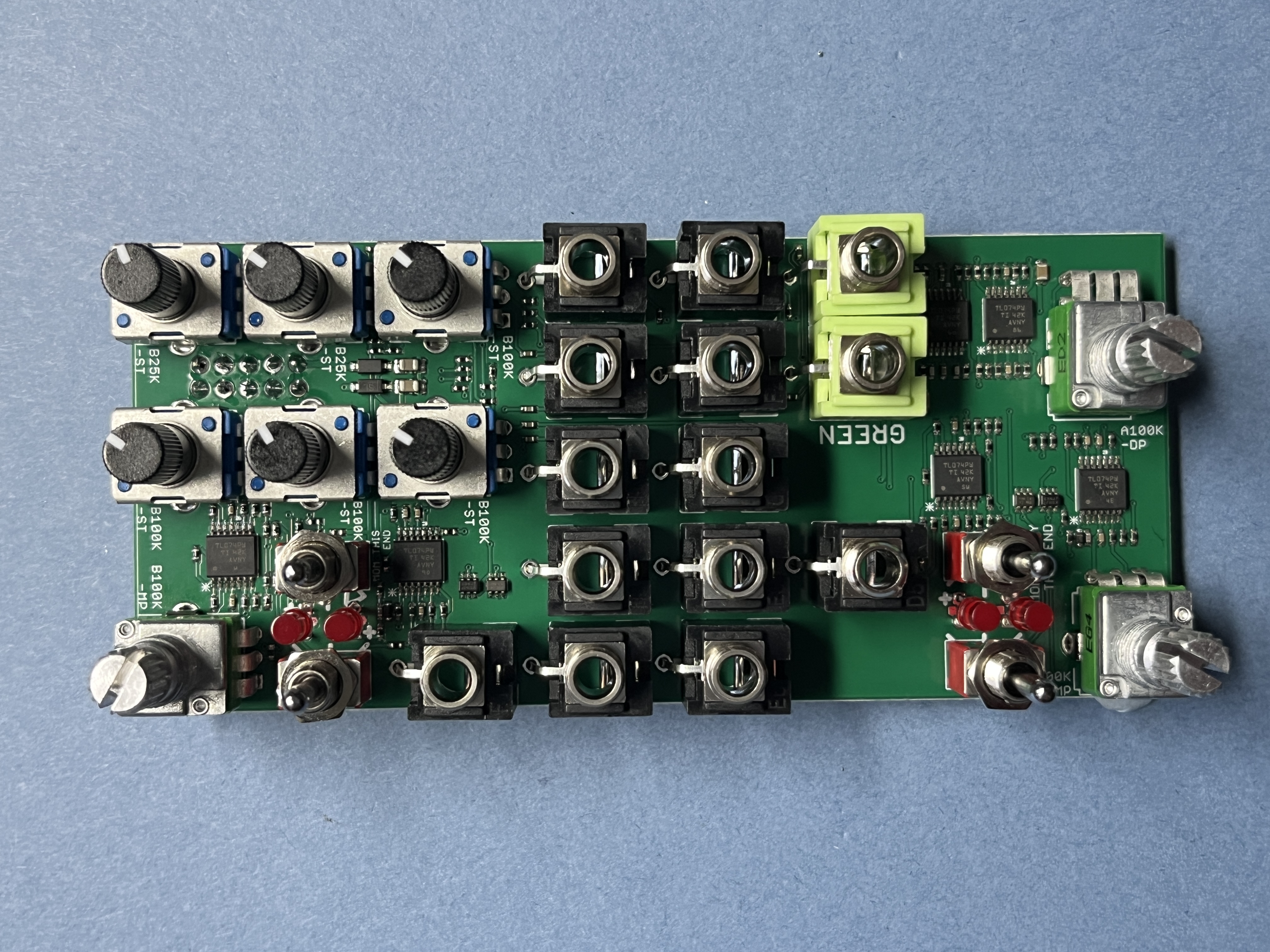
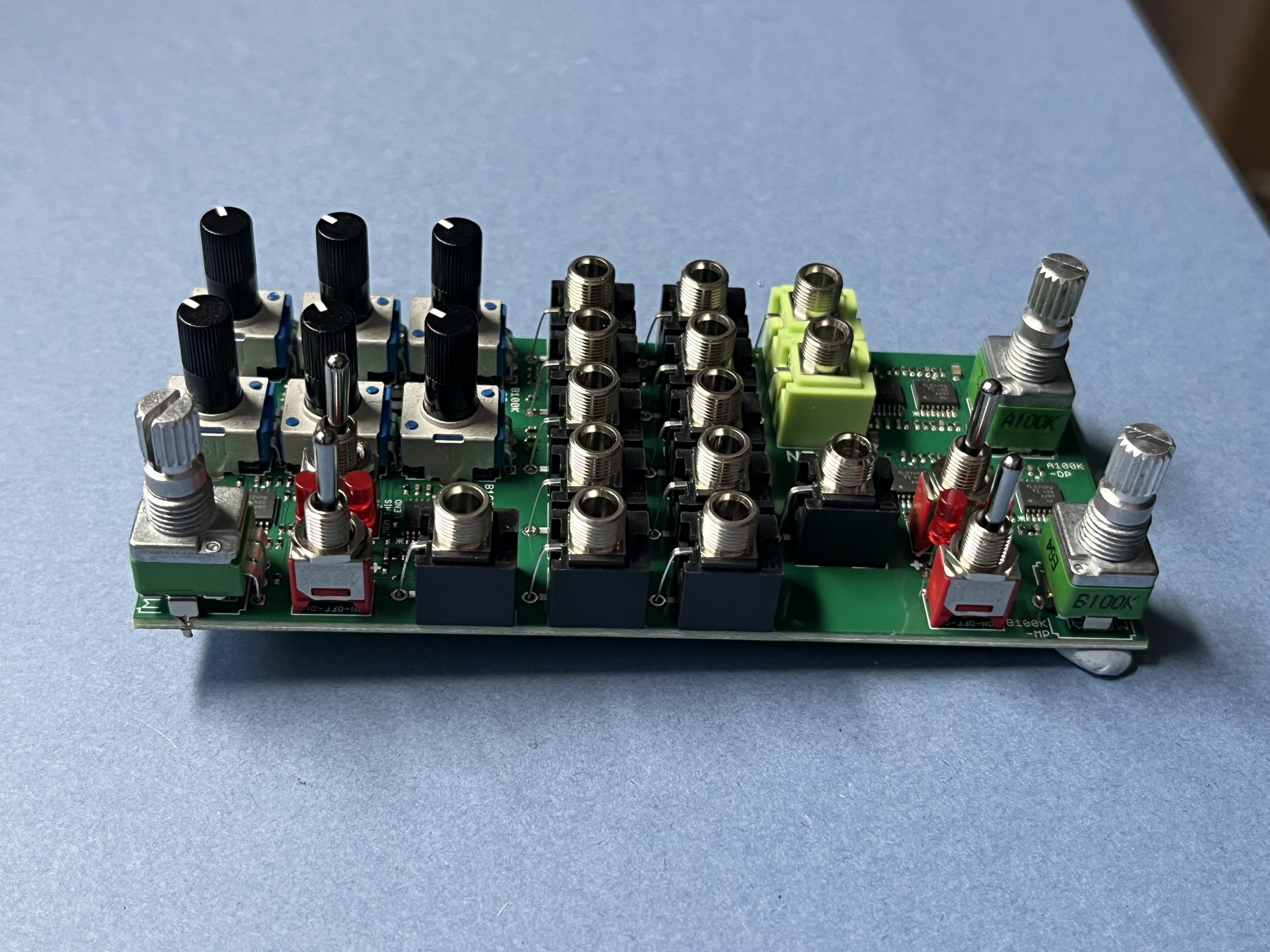
- PCB photos
- This is a dense board, so maybe build it in two stages.
- First, assemble all the pots and sockets.
- Then go back to do the dense switches and LEDs
- There are two types of switches - ON-OFF-ON and ON-OFF-MOM. Check they’re in the right place and the right orientation, as marked on the board.
Building the VCF ←
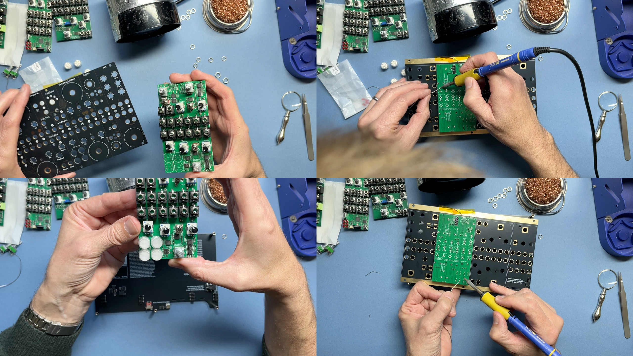
- VIDEO LINK: Building the VCF
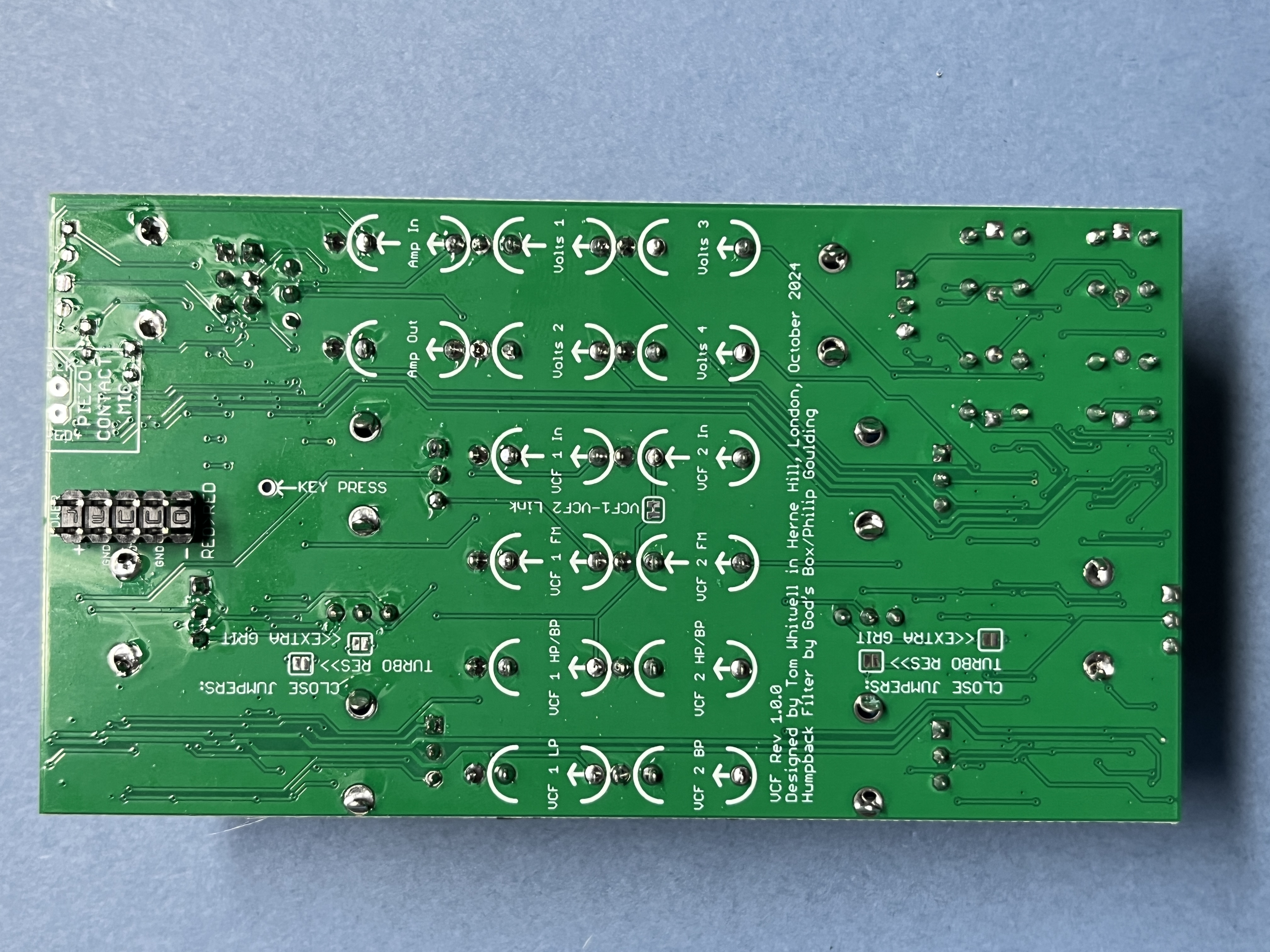
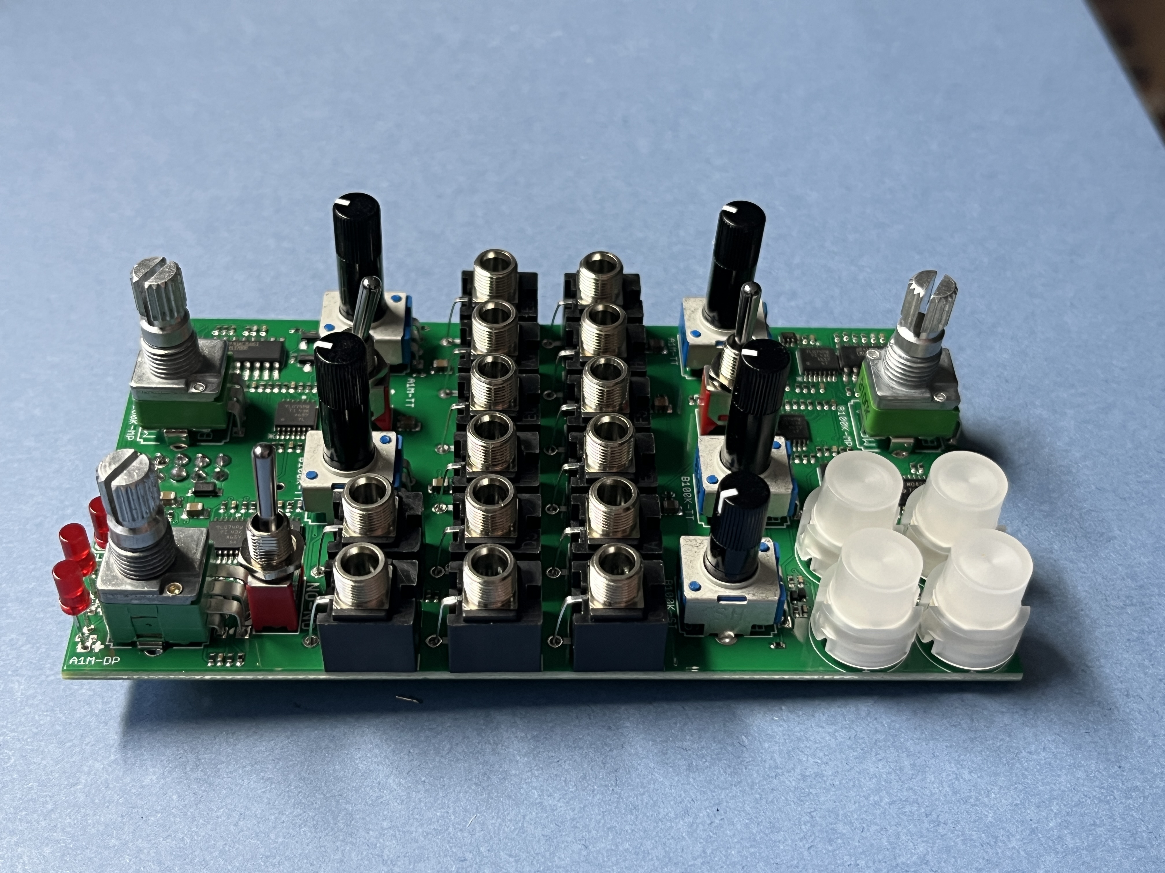
- PCB photos
- This is the fiddliest board mechanically
- The ON-ON switches are tricky to nudge through the panel. You can try balancing them in the centre position, or just jiggling them a bit.
- The easiest method is to assemble in two stages. First do the sockets, LEDs and switches. Then take the panel off and do pushbuttons.
- The pushbuttons have one flat side, which is clearly marked on the PCB.
- The pushbuttons need to be held in place before they’re soldered. I use a little finger to push them up from behind, soldering one of the mechanical pins before checking that they’re moving smoothly. You might also use blu-tack to hold them in place. Take it slow.
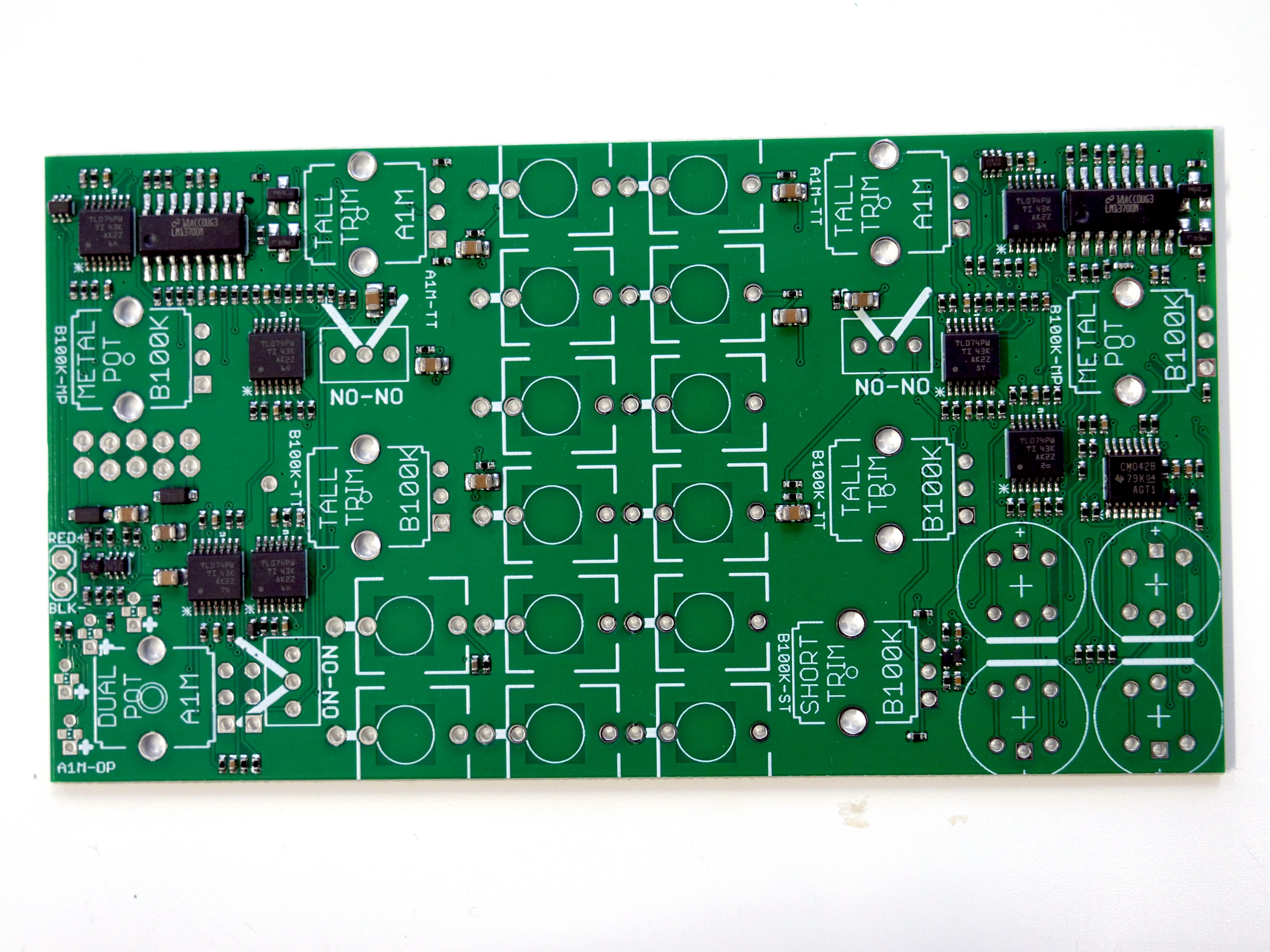
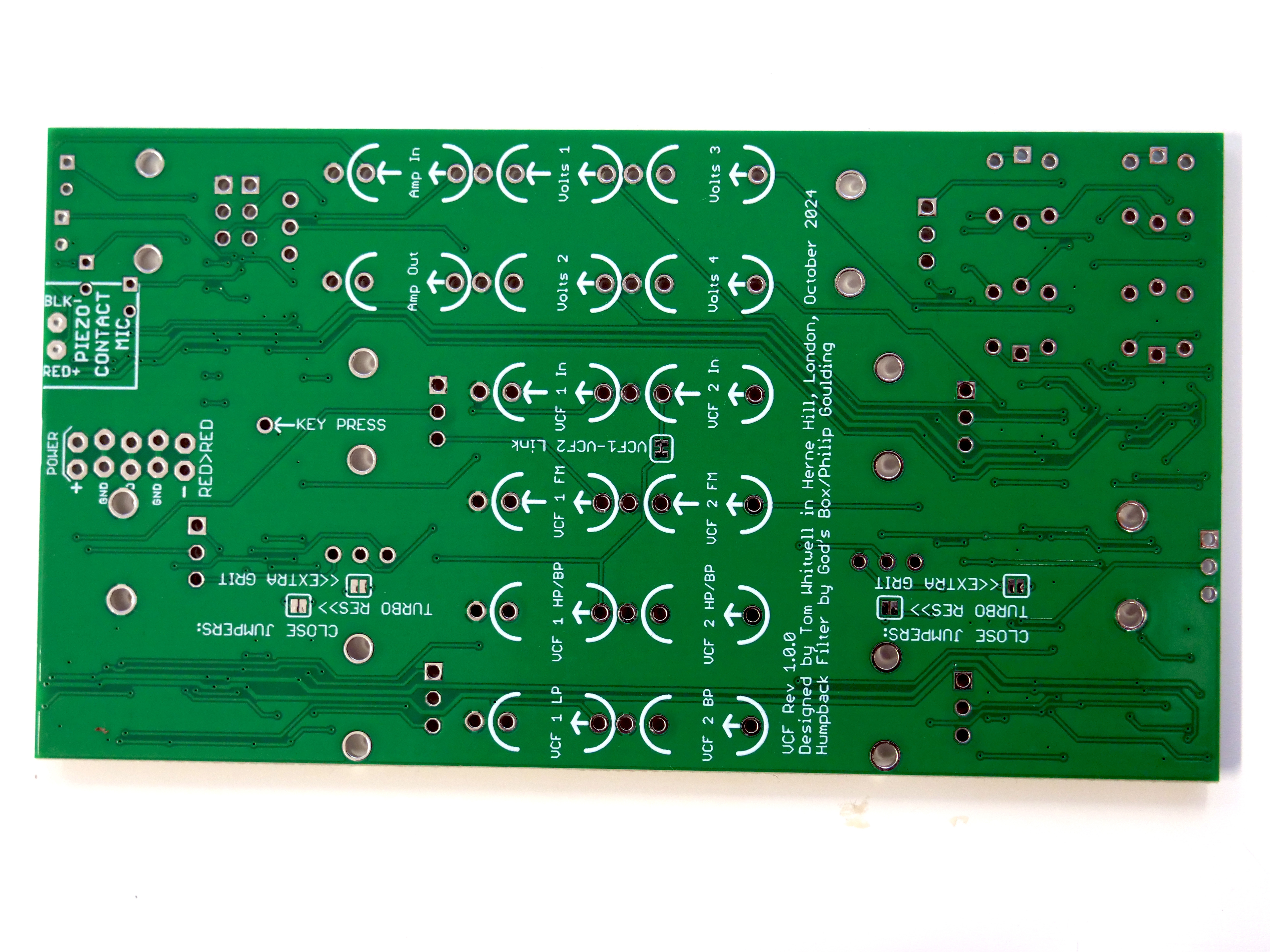
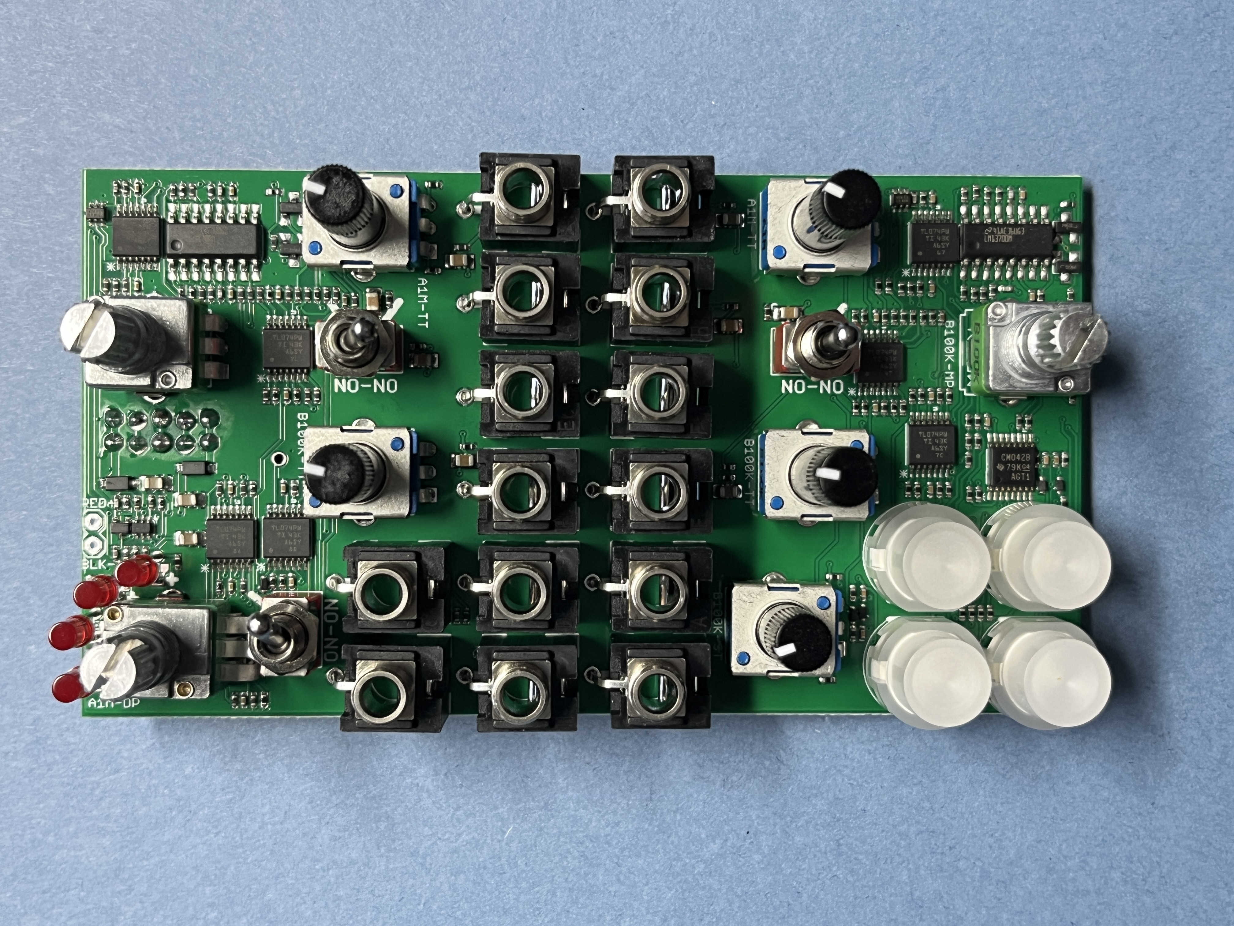
Putting it all together ←
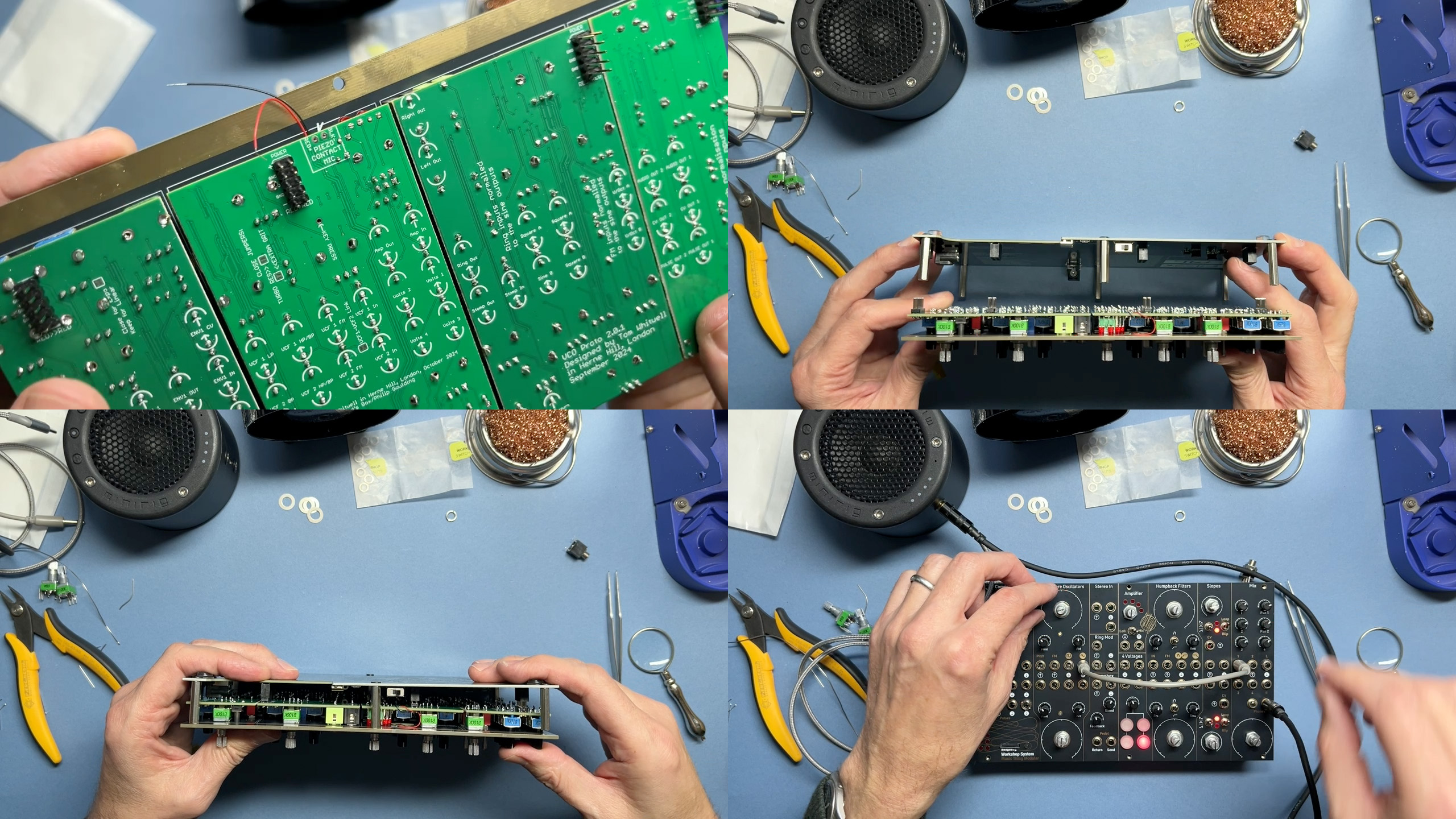
- VIDEO LINK: Putting it all together
- Once the boards are complete, you can assemble the whole thing.
- I’d suggest attaching the boards to the panel with just a few hand-tightened nuts and soldering on the piezo microphone (ensure black goes to black and red goes to red)
- Then carefully mount the panel onto the PSU. Be particularly careful when later removing the board from the PSU — the connectors are easily bent.
- Connect power and test the board. Test details in the quick start guide.
- If everything is working, add nuts to the pots, switches and sockets, and screw the front panel to the spacers.
- Congratulations, you’ve made a Workshop System.
- Enjoy playing with it, and at some point you can think about Calibration.
Troubleshooting ←
If something isn’t working…
- Do not poke anything metal onto powered PCBs The PCBs contain hundreds of very small components, and in some places, +12V and -12V traces near components that can only handle +3.3V signals. If you try to test the boards with multimeter probes while the system is powered up, there is a significant risk you’ll destroy components and/or the power supply board. If you’re concerned that something doesn’t work, contact [email protected] and send photographs.
- Slopes don’t loop If neither Slope loops, this is a sign that the USB power supply is not giving 15 volts, just 5 Volts or 9 Volts. Check with another supply.
- Sometimes the Slope LEDs flicker when I touch the switch I’m not completely sure why this happens, but it’s normal.
- Computer doesn’t do anything Computer won’t do anything - no LEDs - until you put in one of the program cards. Turing card will immediately produce a pattern of LEDs, Reverb+ card is fun for testing sound in and out.
- An LED doesn’t light Most likely that LED is not properly soldered, or has been soldered the wrong way around. Inverted LEDs in Slopes behave very oddly.
- Computer won’t connect to a computer Before doing anything else, ensure that your USB-C cable can pass data. Some cables only pass power.
- A module behaves strangely: too loud, out of control Sometimes this is a sign that a potentiometer pin hasn’t been soldered, or is short-circuited.
- A module is silent or doesn’t pass audio This can happen when an input or output socket either isn’t soldered or is short-circuited to ground by a blobby solder joint.
- The PSU makes a whining noise This is a sign there is a major short-circuit somewhere in the power circuitry, so a module is pulling much too much power. If you have a eurorack power cable, you can power up each module individually, to identify the culprit.